
Don't know as even when the r 18 at irf 610 is shorted there still is no bias eek. So I am out of ideas for now.
Perhaps go through the entire board and check that the resistor values are correct and are in the right locations.
Whether you bought it assembled or assembled it yourself perhaps it is work a double check?
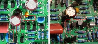
I suggest that since some of the color rings look different from an Ebay photo of what looks like the same version of the L7. But it is really hard to see in the photos. The left photo is from Ebay and the right photo is yours. I don't know if there are any changes or updates in the values.
Edit: I just noticed that one has a copyright date of 2017 and the other 2018. So perhaps just different versions with different values.
Attachments
The specs certainly seem to be unrealistically optimistic. I agree, one pair of devices won't work for 56V rails and 4 ohm loads. As this drives the transistors very close to the SOA line, that does not allow for reactive load lines.
Peak current for 300W / 4ohms is 12.2A. Average current 3.9A per side, so input power is 437W. Assuming a resistive load line that leaves 137W of dissipation in the transistors.
That is just at peak output and maximum efficiency. Peak dissipation in the devices can be higher.
Another of my rules of thumb is that the transistor dissipation needs to be based on half-power square waves as a worst case scenario. That means pumping out 28V into 4 ohms, or 200W, and 200W of transistor dissipation. I would anticipate at least 4 devices in parallel aiming to dissipate 50W each(max) for such a design.
With 0.83C/W thermal resistance in the transistors, 100W (each) cannot easily be achieved. That's a big heatsink.
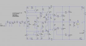
The circuit in the first post also has some errors I think. The PMOS transistor seems upside down and the bias to the gate taken to the wrong supply line?
Not only that but peak currents of 12 are pretty ferocious. It will need thick cables, and could cause problems if the capacitors aren't highly rated. Either from parasitic inductances (in the wiring - large currents generate larger voltages) as well as ripple current.
Peak current for 300W / 4ohms is 12.2A. Average current 3.9A per side, so input power is 437W. Assuming a resistive load line that leaves 137W of dissipation in the transistors.
That is just at peak output and maximum efficiency. Peak dissipation in the devices can be higher.
Another of my rules of thumb is that the transistor dissipation needs to be based on half-power square waves as a worst case scenario. That means pumping out 28V into 4 ohms, or 200W, and 200W of transistor dissipation. I would anticipate at least 4 devices in parallel aiming to dissipate 50W each(max) for such a design.
With 0.83C/W thermal resistance in the transistors, 100W (each) cannot easily be achieved. That's a big heatsink.
The circuit in the first post also has some errors I think. The PMOS transistor seems upside down and the bias to the gate taken to the wrong supply line?
Not only that but peak currents of 12 are pretty ferocious. It will need thick cables, and could cause problems if the capacitors aren't highly rated. Either from parasitic inductances (in the wiring - large currents generate larger voltages) as well as ripple current.
Last edited:
But it is really hard to see in the photos.
I have found that aliexpress often has higher resolution images vs ebay.
What is the drain to source voltage on the IRF610?
I just took the L 7 out and will not use that ****. Ordered other amp boards from Banggood. With 2 sets Mosfets.
It seems to me like the kits and assemblies being discussed are "knock-offs" - i.e. assemblies by other sellers/suppliers who make cheaper copies, with or without original PCBs. If you doubt this likelihood, I suggest that you follow LJM's comments regarding his other designs and competitors too. It's a big problem for him.
I have managed to buy several LJM original kits (and a few fakes) through the usual global platforms but if you want to buy LJM's kits and assemblies exclusively and so avoid the confusion and deception, you need to deal with LJM's own store at Taobao, the Chinese language selling platform. Unfortunately, you'll also need to translate to/from Simplified Chinese language plus organise shipping and taxes yourself. Good luck with that.
Otherwise, pick and choose your kits and assemblies very carefully. Saving say, 25% by buying from a cheap seller makes no economic sense if what you get is a bunch fake or poor substitute semis, under-rated resistors and diodes, relays etc. which is likely where the 25% saving comes from. Stupid really, because when you've replaced the components with known good ones, your cost just exceeded the genuine product - if you could be sure of sourcing it, that is.
In other words, if you prefer to buy than DIY, at least get the buying part right and don't assume that what think you see in pics is fact. Pics are not specifications; just visual indication or prompts of what we may be looking for. Trained professional buyers have been fooled many times in the electronics business, so what chance does an inexperienced amateur have?
There is no bias adjustment and bias is Zero. Distortion is 0.3 %
So without adjusting the bias to a higher level, the distortion of 0.3% is high.
Thank you
Hi I'm new here, thanks for accepting , i have a L7 amp board, would this work with +-65 Vdc on a 500w 4 ohm speaker ? ?What would be the rep[lacement for c1815 which cab stand 65V ?? ThxWhen testing this amp with a +/-55V power supply (my observations also hold for lower supply voltage), I found that there is a severe fire risk, as soon as the SOA or max junction temperature of the IRFP9240/ IRFP240 is exceeded. The NCC5551 (equal to 2N5551 with different pin-out) in the "totem pole" exploded and cought fire and the 2N5401 in the totem pole became shorted.
This failure mode is a result of the IRFP9240/IRFP240 exceeding the operating junction temperature limit, 150°C, according to the data sheets or SOA limit, which is about 5A at 55V Drain_Source voltage with 10ms pulsed signal (100Hz). According to LJM, +/-55V rail supply is allowed for the L7 amp. With thermal resistance junction-case of 0.83 W/°K, the L7 amp's heat sink is very critical and sufficient heat dissipation very difficult to accomplish for 50W and more into 4 Ohms.
Conclusion:
The L7 amp is not "safe" to use for >50W into 8 Ohm load or >30W into 4 Ohm load because the MOSFET' thermal resistance junction-case is 0.83 W/°K. To maintain at 50W (sinus) a junction temperature of <150°C it requires a total thermal resistance (incl. heat sink) of 0.5 W/°K or better. That however, is not possible (or only possible for a short time) with a single power transistor pair, given the high MOSFET junction-case thermal resistance of 0.83 W/°K (data sheet). This is even so if the heat sink's thermal resistance is less than 0.5 W/°K.
Safety Precautions:
1) Because there is no resistor in the power amp stage in series with the source or drain, a very high current will flow in case a power MOSFET becomes internally shorted. Usually, the resistor would open in such case to prevent the worst. Not here however, because the L7 circuit comes without it. Therefore, it mandatory, that the rail supply voltage lines +Vcc and -Vee are protected by a fuse each (fast type), which opens when a specified current is exceeded, i.e. 1.5 amps). This is actually "good practice" and would not need to be highlighted, but can be forgotten sometimes.
2) To avoid that the small signal transistors NCC551 (and/or 2N4501) can explode and burn (with an open flame) in case of internal short of a power-MOSFET, I can only recommend to LJM (if he reads this) to consider including two 10k resistors as indicated in the modified schematic attached below. It was tested in LTSPICE and has no negative impact on the amp's performance (output power, THD, intermodulation, all remains as before). In a power-MOSFET fail incident, these resistors would limit the current to a few milliamps, so that no danger could result from the totem pole transistors anymore.
Other Recommendations:
I found that the THD with the L7 is low up to 1 kHz, but can increase significantly up to 0.2% from 1kHz to 20 kHz, due to crossover distortions, depending on how well the MOSFET pair is matched. The bias is fix by the voltage divider resistor pair 9.1k/10k at the bias transistor gate. This is a "safe" configuration, but often not sufficient to cancel the crossover distortion at higher (i.e. 10kHz) frequency. Leaving it up to the hobbyist to adjust idle current himself, may be not a good advice, because within a few hundred ohms only, the idle current goes through the roof and the power-MOSFETs ....bang! I found a good compromise with both voltage divider resistors at the bias transistor exactly 10.0 kOhm. They must be measured and selected for being precisely the same, tolerance of 1% is not enough. Therefore, I am not sure if that is a practical solution for a DIY kit. Nevertheless, it provides improvement of THD and IM-distorions.
Further improvement is possible with a 33pF capacitor parallel to the resistor in the NFB-line. In early versions of the L7 the resistor was 10k and the corresponding foot-resistor in series with the NFB electrolytic cap (1000µF formerly) was 330 Ohm. In the newer L7 version the NFB resistor was increased to 33k, the NFB electrolytic cap changed to 470µ and the series resistor with the cap 1k. Thus, a 33pF foil cap parallel to the 33k resistor (formerly 10k) in the NFB improves higher frequency distortion. Why only 33pF? Higher capacities (47pF and up) can cause oscillation.
Perhaps some L7 users find this review useful.
Best Regards
Reinhard
- Home
- Amplifiers
- Solid State
- L7 MOSFET DIY amp kit by LJM