EVENT OPAL setting bias
Hi everyone, I thought that I'd share this situation and ask for some assistance as I "fine tune/optimize" the amps.
While my Event Opal monitors sound okay, I decided to take some measurements.
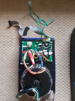
I'm the second owner and given that one heat sink operated noticeably warmer then the other, even at idle, I wanted to ensure bias is set correctly/ optimally.
And, I have some reason to believe that the first owner had been messing around inside...
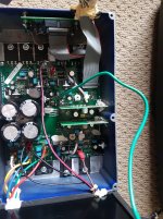
There is no trim pot for offset, only for bias (white vr bias, the black vr is for output level to balance freq response)
The monitors have been discontinued for a few years.
The manufacturer set bias according to crossover distortion ( AP analyzer).
I only have access to an oscilloscope.
* The values across the 0.05 ohm resistors on the left side are suspect.
Are the other values "normal" or indicative of something not quite right?
What is the best/ optimum way to set bias for these amps?
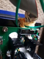
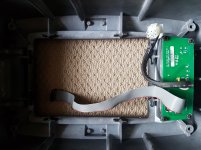
See attached measurements, photos, schematics,etc...
Cheers
SW")
Hi everyone, I thought that I'd share this situation and ask for some assistance as I "fine tune/optimize" the amps.
While my Event Opal monitors sound okay, I decided to take some measurements.
I'm the second owner and given that one heat sink operated noticeably warmer then the other, even at idle, I wanted to ensure bias is set correctly/ optimally.
And, I have some reason to believe that the first owner had been messing around inside...
There is no trim pot for offset, only for bias (white vr bias, the black vr is for output level to balance freq response)
The monitors have been discontinued for a few years.
The manufacturer set bias according to crossover distortion ( AP analyzer).
I only have access to an oscilloscope.
* The values across the 0.05 ohm resistors on the left side are suspect.
Are the other values "normal" or indicative of something not quite right?
What is the best/ optimum way to set bias for these amps?
See attached measurements, photos, schematics,etc...
Cheers
SW
Attachments
-
 left amp.jpg894.2 KB · Views: 557
 -
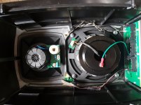 left drivers.jpg667.8 KB · Views: 539
 -
 left ground wires .jpg503.3 KB · Views: 538
 -
 left input.jpg758.1 KB · Views: 476
 -
 left ps.jpg961.3 KB · Views: 524
 -
datasheet.pdf240 KB · Views: 171
-
opal amplifier measurements.pdf50.2 KB · Views: 207
-
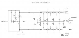 low freq amp schematic.jpg147.9 KB · Views: 539
 -
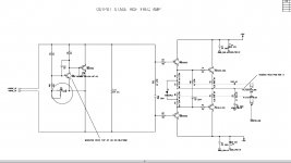 hi freq amp schematic.jpg137.2 KB · Views: 505
Last edited:
A few oddities there for sure.
Tweeter amps are rather on the underbiased side, <10 mA in particular seems very skimpy... normally 20 mA is about the minimum, and you'd think that if crossover distortion matters anywhere, it would be the tweeter. Theoretical optimum is between 13 to 26 mV per emitter resistor. Now I don't know whether the crossover components visible will perform an impedance transformation and thus potentially make the tweeter a lighter load, but still.
Why would one side have tweeter hiss while the other one doesn't? Must be a problem upstream (or the quiet side has a protection relay contact issue, but you'd probably have noticed the difference in FR..). Got more of the schematic?
I think the last two transistor pairs in the woofer amp are only supposed to kick in when high current is demanded, otherwise the first pair of finals will support the load just fine already. (Sorta like Class G.) That makes the side with the two transistors having >100 mA quite suspect... these may have been replaced at one point, clearly with something that wasn't a good match for the remaining originals. It's also the only power stage with DC offset substantially differing from 20-odd mV, so I reckon it's had an input stage transistor replaced as well (probably the one on the feedback side which has a tendency to get damaged if the amp has a meltdown). On the whole this smells like a past repair, perhaps not to the highest standard...
Some pretty impressive kit, these. They certainly warrant some TLC.
Doesn't seem logical to me, the crossover high harmonics are mainly ultrasonic from a tweeter amp. The other driver amps will be producing more harmonics in the audible range, and starting from a higher amplitude signal to start with.and you'd think that if crossover distortion matters anywhere, it would be the tweeter
Harmonics, maybe - but what about IMD?
Besides, we are talking a system crossed over at 1.6 kHz with high order. The tweeter amp isn't just sitting there and twiddling thumbs. The woofer amp is more critical than a sub amp but less critical than something fullrange.
When I'm thinking crossover distortion, I think of it as something that can be equally as nasty at low amplitudes as at higher ones, and even substantially worse if considerably underbiased. Now tweeter sensitivity tends to be higher than woofer sensitivity (and this woofer is super long throw), plus it gets less signal power to begin with, so guess who is more likely to expose such amplifier issues. Going by how common issues with hiss are, active speaker manufaturers do not seem to be the ones to use series attenuation resistors very often.
are you certain about the schematic....
Hi there. I've never posted to a forum so be gentle with me please.
I just purchased an pair of Event Opals. knowing that one speaker amp was blown, I got them at a substantially reduced price thinking How hard can it be to repair?? If I could only turn back time. Please understand...I have no formal schooling in electronics and but I'm a jedi with a solder iron
In any event, Are you certain about the orientation of the JE340 transistor in the first stage of both the hi frequency and low frequency amp?? I tried getting a Schematic from Event (now RODE) in Australia. I guess it's a issue of national security for the Aussies not to offer schematics on discontinued gear.
Both the working speaker and the damaged one have this particular transistor oriented so that the emitter of the JE 340 is connected to the base of the JE 350. making the collector of both transistors tied to each other.
Your schematic shows these connections flipped around.
Is this a self created schematic or did it come from Event?
I'm not sure what happened to this speaker, but numerous components were inihilated when it blew. The daughter cards for the hi freq amp was charred taking out the TLO72 on board. many of the Low freq amp resistors and power transistor were toasted as well. Just thought I'd mention it...
You could flip C and E in the MJE350 and it would technically still work... not sure about the performance of the C-B pn junction compared to the normal E-B one, of course, but either way C-E voltage in this bias spreader circuit is so low that you can get away with reverse operation.
I hope you've managed to make some inroads... dealing with charred PCBs is no fun.
I hope you've managed to make some inroads... dealing with charred PCBs is no fun.
I just discovered this thread.
The schematics posted are OK, I think it is not worth to answer old questions (there are wrong comments about the bias, etc.).
Regarding the noise, there should not be audible hiss in normal listening conditions unless the pre-amp board is damaged, sadly it is pretty complicated to disassemble the speakers to work on the preamps, there are a lot of NE5532AN used in the pre. I modified mine by-passing the tone controls and replacing the dual opamps with OPA2604 (10 years ago).
- Home
- Amplifiers
- Solid State
- Event Opal Amps Puzzle