Both IRFP240/9240 work or Fairchild FQA’s work too. There are many basic hexFETS that should work. IXYS will have some big ones too.
Both of those were too few in stock for 2 pairs.. I ordered what I could get, and I think I have some IRFP's somewhere that I can use too, but I'm a bit worried about using them with so much dissipation in the long run.
A question to the guru's:
What is the 'weakest link' for PSRR of the AN amp? Would a separate supply to the front and do much for hum? (I have a separate front end supply with Cap-multiplier in the chassis I'm thinking of using)
@andyr: glad to hear you're still happy with it. Interesting speaker setup you built too. Have you tried arranging the drivers with the tweeter in the center (MMTMM)?
@andyr: glad to hear you're still happy with it. Interesting speaker setup you built too. Have you tried arranging the drivers with the tweeter in the center (MMTMM)?
No actually ... I haven't. But it would be relatively simple to get my 'metal man' to make up 4x new 'U-frames' to support the drivers in an MMTMM configuration.
What benefit do you suggest this will give me, Rf?
Andy
To answer my own PSRR-question:
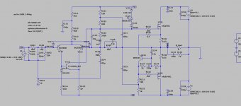
I tried adding 1V 100Hz ripple to the supplies in the sim, and had 4mV(p-p) on Vout, then I fed the front end separately (according to the attached schematic), and ripple dropped to 0,2mV(p-p). It seems like it could a cost effective way to reduce hum, instead of going with CRC, cap multipliers etc on the main supply.
I will see what I end up doing, but just posting to share my findings.
Running the complete audio band indicates more than 30dB improvement through most of it, but a bit less at HF. Connecting R132 to the front end supply too only gives improvement below 10Hz it seems.
Attachments
Last edited:
No actually ... I haven't. But it would be relatively simple to get my 'metal man' to make up 4x new 'U-frames' to support the drivers in an MMTMM configuration.
What benefit do you suggest this will give me, Rf?
Andy
Just thinking that the directivity/off axis FR would be more symmetrical, get the lower midwoofers further from the floor etc. I assume you would make them higher to still have the tweeters at ear level.
I'm thinking it could (possibly) improve imaging, and as you say, it should not be so hard to give it a try. I think you would have to tweak the DSP-corrections though. I would probably do it, because I like tweaking stuff
")
Sorry about offtopic (again).
RF,
Good improvement running separate supplies for the front end, thanks for the suggestion. But because of the way the output stage is driven at the gate of the nmos (high drive, rather than low drive), you could throw away 2V from each rail and thus supply the front end from a simple RC.
In truth, the LTP is well regulated already, but the negative rail is wide open and a regulated supply at R114 and R115 would be very beneficial.
HD
In truth, the LTP is well regulated already, but the negative rail is wide open and a regulated supply at R114 and R115 would be very beneficial.
HD
Interesting Hugh - but how does one modify the PCB to be able to provide a regulated DC supply at R114 & R115?
Pesumably this regulated supply must come from a separate PS to the SLB?
Andy
Last edited:
Just thinking that the directivity/off axis FR would be more symmetrical, get the lower midwoofers further from the floor etc. I assume you would make them higher to still have the tweeters at ear level.
OK - interesting.
(Yes, tweeters would remain at the same height, I'm thinking.)
I'm thinking it could (possibly) improve imaging
I agree.
So a worthwhile investigation.
I think you would have to tweak the DSP-corrections though.
Well, easy enough to do an REW sweep and see.
Andy
Interesting Hugh - but how does one modify the PCB to be able to provide a regulated DC supply at R114 & R115?
Pesumably this regulated supply must come from a separate PS to the SLB?
Andy
The brute way could be just lifting the low end of the resistors, tie them together and solder a wire to them.. Since I don't have the PCB's I can't make other suggestions like cutting traces etc. Maybe even an onboard cap multiplier would be doable?
My separate front end supply runs on the same (main) transformer windings, but has its own rectifier, smoothing caps, and simple cap multipliers for each rail.
What I have not looked at is what happens at power up/down, short power cuts in the grid etc. There can be strange (and destructible) transients or DC out in some cases when the rails are not 'syncronized'.
@AKSA : I always try to find the cheapest way, beefy regulated and filtered supplies are usually complex and expensive
I just did a sim with only R114 and R115, and it's does most of the PSRR improvement. From 100Hz down, it's a little bit worse than the one I did, but I think most of the noise is from 100Hz up anyway. Only a few dB at 50Hz.
Last edited:
I tend to worry what happens if there is a short power out, it sometimes happens here during storms etc.
I did a short sim on what happens if the front end has voltage when the main supply is turned on. This is what I think the situation would be if power is gone 1-2sec. The caps on the front end supply drains slowly, while the caps for the outputs drain quickly because of Iq.
Short power outage:
1. both front end rails on a separate supply, and that seemed fine.
2. only R114 and R115, and that was a bit nasty with a -12V dip on Vout.
Also turn on sim:
3. std front end supply at turn on indicates a -14V thump (around 20ms) at turn on. Does this correlate with reality for those of you who built the amp if you tried it without output relays?
4. 'filtered' (I simmed 1000u/100ohm RC) front end supply (both rails) indicates a -20V thump at turn on
5. filtered negative only indicates a -14V thump at turn on
Last edited:
Hello All,
I'd love to get some feedback on a mobile version on this amp (or the Alpha 20). Specifically building a 12v step up power supply. I know heat and idle draw will be an issue, but I'm willing to sacrifice heatsink size.
Any advice or insight would be appreciated.
Thanks!
Jon
I'd love to get some feedback on a mobile version on this amp (or the Alpha 20). Specifically building a 12v step up power supply. I know heat and idle draw will be an issue, but I'm willing to sacrifice heatsink size.
Any advice or insight would be appreciated.
Thanks!
Jon
I wonder if something like this would suffice
PULS CD5.243 | In: 12V DC, Out: 24V DC, 4A DC/DC converter
PULS CD5.243 | In: 12V DC, Out: 24V DC, 4A DC/DC converter
Yes, I think it would work. You would need two for each module, or maybe two larger units for the two amp channels. And you'd have to know that the output could be configured for +24V and -24V rails. And lastly, you'd have to know how much capacitance they can support, SMPS supplies can be intolerant of high capacitance on the output.
However, you would have to cool it, AND the amp, and that's no small task in an automobile. Since temperatures can be very high in cars, I would suggest a fan which is switched on when the temperature rises above about 60C.
HD
However, you would have to cool it, AND the amp, and that's no small task in an automobile. Since temperatures can be very high in cars, I would suggest a fan which is switched on when the temperature rises above about 60C.
HD
On top of the car. You'll have natural air flow...
I could then duct the heat back into the car during the winter months
Yes, I think it would work. You would need two for each module, or maybe two larger units for the two amp channels. And you'd have to know that the output could be configured for +24V and -24V rails. And lastly, you'd have to know how much capacitance they can support, SMPS supplies can be intolerant of high capacitance on the output.
However, you would have to cool it, AND the amp, and that's no small task in an automobile. Since temperatures can be very high in cars, I would suggest a fan which is switched on when the temperature rises above about 60C.
HD
I would definitely run this with a fan(s) and shroud
I found these cheap, wondering if i should pick up 4 of them to test with.
LPD301-012-24-VC-200 PDF Datasheet - Natel EMS - Datasheets360.com
Sorry if this is in this thread, but does anyone know what is the max current draw per channel on 4ohm version of this build?
Thanks for the DC converter pdf! They look great......
The 4R AN Class A would use 3A quiescent, and so the max current would be double this at the peaks. The nmos will pass more than this, up to around 6A, but the pmos will be restricted to 2Iq.
BTW, you'd be crazy to put such an amp any where else but at the rear of the car. Front (hood) area is VERY hot, passenger cell would warm up necessitating more AC use, but the rear could take quite a bit of heat and in truth with carefuly heatsinking some of the heat could be transferred handily to the base of the trunk and then to the airflow under the vehicle.
Hugh
You could put the heatsink beneath an air scoop similar to the one on the roof of a Stratos (right above the rear view mirror).
Lancia Stratos HF Gr.4 at Rally Legend! - LOUD Ferrari V6 Engine with Single Straight Pipe Exhaust! - YouTube
Lancia Stratos HF Gr.4 at Rally Legend! - LOUD Ferrari V6 Engine with Single Straight Pipe Exhaust! - YouTube
- Home
- Amplifiers
- Solid State
- Alpha Nirvana 39w 8ohm Class A Amp