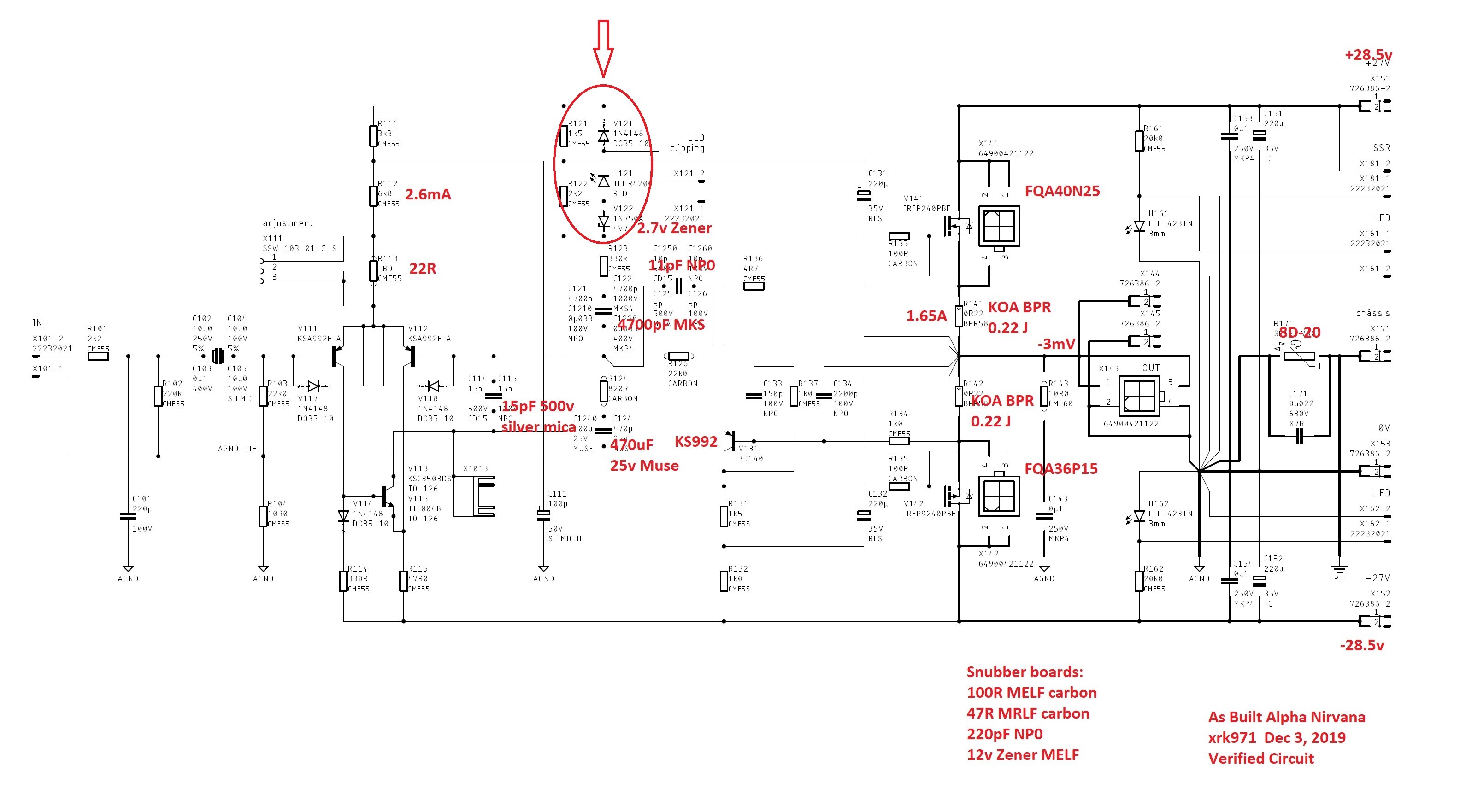
Are you sure that the directions of these diodes are correct?
Yes, it seemed strange to me - but I just connected up the diodes the way they are shown on the PCB ... and the red LED goes on at clipping.
")
Andy
Hugh,
Forgive me if I'm off base. The key to understanding how the gate might go higher than the positive rail has everything to do with bootstrap capacitor C131. If there is a relatively abrupt increase in output voltage that same increase will be seen at the positive side of C131 while the voltage across the cap won't change much.
Forgive me if I'm off base. The key to understanding how the gate might go higher than the positive rail has everything to do with bootstrap capacitor C131. If there is a relatively abrupt increase in output voltage that same increase will be seen at the positive side of C131 while the voltage across the cap won't change much.
HI Jan,
The drive at the gate can exceed the positive rail, but the upper nmos won't turn on until the source gets within about two volts off the rail. At that point, the gate would be 2.5V above the rail, and to prevent the nmos turning off because of dropping Vds, better to put in these diodes to drain drive to the positive rail and turn off the nmos at its gain, allowing recovering when gate potention drops and gate turns on the channel as drive falls.
At least, that is my understanding? Is this wrong?
Beautiful build of the AN you are doing, looks like a DartZeel!!
Hugh
gate drive is higher than 4V Over the positive rail.
HD
Can this ever be possible?
Yes, Caglarm, a bootstrap means that when the cap is charged at idle it will hold around 15V across it. Since the negative side (on the positive rail bootstrap) is connected to the output, if it rises to +24V (peak voltage wrt ground) then the bootstrap cap will drive up the voltage at its positive electrode because it holds a lot of energy and can overcome the positive rail to boostrap resistor, 1.5K in this case.
So, can see a positive rail at the bottom of the bootstrap rising ABOVE the upper rail, it is quite normal and a useful way to drive a mosfet right up to its limits on the rail.
Hugh
So, can see a positive rail at the bottom of the bootstrap rising ABOVE the upper rail, it is quite normal and a useful way to drive a mosfet right up to its limits on the rail.
Hugh
Yes, Caglarm, a bootstrap means that when the cap is charged at idle it will hold around 15V across it. Since the negative side (on the positive rail bootstrap) is connected to the output, if it rises to +24V (peak voltage wrt ground) then the bootstrap cap will drive up the voltage at its positive electrode because it holds a lot of energy and can overcome the positive rail to boostrap resistor, 1.5K in this case.
So, can see a positive rail at the bottom of the bootstrap rising ABOVE the upper rail, it is quite normal and a useful way to drive a mosfet right up to its limits on the rail.
Hugh
Thank you. I understood properly now .
Hi X,
10 days ago, I posted on the SLB thread that I had finally fixed the fault on one of the SLBs in one of my amps.
During this process, I also decided to bypass the Molex connectors on the 4x SLB boards and solder the off-board transistor wires directly to the PCBs.
(This amp is now plugged in and producing sweet music on my R channel - powering the mid panel (3.2 ohm) and ribbon (2 ohm).)
Then I moved on to the other amp - which had simply produced 'crack', 'crack', 'crack' when I plugged into the L Maggie. (Even though I had tested it with a sig-gen & CRO before plugging it in!)
After much stuffing around - including blowing a ribbon (which will cost me USD500 and means that I will be without the L Maggie for 2 months, whilst it's being repaired by the importer) - I found that the 'crack', 'crack', 'crack' was due to the Molex connector on the -ve mosfet side, not making good contact ... which caused a positive-half only square wave to be output (instead of a sine wave).
This is a major catastrophe - which could've been entirely averted if you/Jan had used spades to connect the off-board mosfet wires, not Molex connectors. There's a lack of logic here which I cannot understand. You did use spade connectors for all the other high current connections:
* traffo secondaries on the SLBs
* DC rail outputs & chassis earth on the SLBs
* and DC rail inputs & chassis earth on the AN boards.
Given you did this ... I find it strange you decided not to use spades for the similarly high current connections to:
* the offboard transistors on the SLB boards
* and the offboard mosfets on the AN boards?
I believe I know the reason why you chose Molex connectors - they look 'sexy & sophisticated' - wheres spades are 'crude & ugly'!
It would certainly have made my build easier (and less costly! ) had you used spades instead of Molex connectors. Perhaps you might like to consider it for the next PCBs you design. (Not that I'll probably be building any more amps - these have put me off for life!)
Andy
10 days ago, I posted on the SLB thread that I had finally fixed the fault on one of the SLBs in one of my amps.
During this process, I also decided to bypass the Molex connectors on the 4x SLB boards and solder the off-board transistor wires directly to the PCBs.
(This amp is now plugged in and producing sweet music on my R channel - powering the mid panel (3.2 ohm) and ribbon (2 ohm).)
Then I moved on to the other amp - which had simply produced 'crack', 'crack', 'crack' when I plugged into the L Maggie.
(Even though I had tested it with a sig-gen & CRO before plugging it in!)After much stuffing around - including blowing a ribbon (which will cost me USD500 and means that I will be without the L Maggie for 2 months, whilst it's being repaired by the importer) - I found that the 'crack', 'crack', 'crack' was due to the Molex connector on the -ve mosfet side, not making good contact ... which caused a positive-half only square wave to be output (instead of a sine wave).
This is a major catastrophe - which could've been entirely averted if you/Jan had used spades to connect the off-board mosfet wires, not Molex connectors. There's a lack of logic here which I cannot understand. You did use spade connectors for all the other high current connections:
* traffo secondaries on the SLBs
* DC rail outputs & chassis earth on the SLBs
* and DC rail inputs & chassis earth on the AN boards.
Given you did this ... I find it strange you decided not to use spades for the similarly high current connections to:
* the offboard transistors on the SLB boards
* and the offboard mosfets on the AN boards?
I believe I know the reason why you chose Molex connectors - they look 'sexy & sophisticated' - wheres spades are 'crude & ugly'!
It would certainly have made my build easier (and less costly!
) had you used spades instead of Molex connectors. Perhaps you might like to consider it for the next PCBs you design. (Not that I'll probably be building any more amps - these have put me off for life!)Andy
I did check that the output was sine waves (using sig-gen & CRO) before taking the amp upstairs and plugging it in, Jacques. (That's the best way I know of checking that the connectors … are connecting! )
The minor bumps involved in lifting the amp of the floor … then putting it down on the floor upstairs … then moving it into position behind the Maggie panels - must've dislodged one or more of the connections. That's all I can think of, anyway.
And as to "old speakers found on the curb " - you must live in a much more exclusive suburb than I do!
Andy
)The minor bumps involved in lifting the amp of the floor … then putting it down on the floor upstairs … then moving it into position behind the Maggie panels - must've dislodged one or more of the connections. That's all I can think of, anyway.
And as to "old speakers found on the curb " - you must live in a much more exclusive suburb than I do!
Andy
Andy,
I understand you bought a crimper for these Wurth connectors?
If they do not connect after moving around a little, it tells me that there is a crimp issue.
I don't want to promote or denigrate the Molex connectors, but most people seem to have no issues with them and I'm tempted to say that there may be an issue with your technique.
It's a bit like smd components; you have to get used to them.
Hugh
To me, using whatever connector in a DIY amp does not make sense at all.
Nothing is as reliable as a good (!) solder joint, and a DIY'er has the time to solder instead pushing/pulling connectors.
Most commercial amps have connectors, obviously for ease of assembly in the manufacturing process.
My trusted Rotel RB890 power amp has no connectors though it is not "highest end".......all connections, from signal input to PCB, power supply to PCB, PCB to loudspeaker terminals, are soldered.
Maybe that's why it refuses to die after over 25 years of daily service...
Last edited:
Andy,
I understand you bought a crimper for these Wurth connectors?
Hugh
Yes I did indeed, Hugh - one of the crimpers which X suggested.
If they do not connect after moving around a little, it tells me that there is a crimp issue.
I don't see how you get to this conclusion, Hugh.
The crimper locks the wire to the female pin connector - it doesn't do anything in terms of:
* the way these female pin connectors fit into the Molex/Wurth male header
* or the way the female pin connectors fit onto the pins.
Andy,
I don't want to promote or denigrate the Molex connectors, but most people seem to have no issues with them and I'm tempted to say that there may be an issue with your technique.
That may well be the case, Hugh.
However, my point is the lack of logic when using spades for the high current traffo connections and DC rail connections ... yet not using them for the high current SLB transistor and AN mosfet connections.
Also, I am interested to know whether the 'Molex MegaFit' connectors that rabbitz mentioned would've been a better choice by X/Jan. Looking them up - they certainly seem to be more robust than the ones X specified in the BoM ... but nowhere near as robust as spades!
Andy
Hello andyr,
I´ve done the layout.
Do you´ve seen spades on PC motherboard? Do you know issue using this connectors from PC builders?
I´m using this connectors, exactly the same, for some aeronautical power supplies: no issue during DO-160 tests!
There is an other issue?!
PS.: MegaFit are 5,7mm pitch instead 4,2mm.
JP
- Home
- Amplifiers
- Solid State
- Alpha Nirvana 39w 8ohm Class A Amp