Thanks, hpro.
Sorry, hpro - I don't understand what you're getting at, here?
Andy
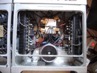
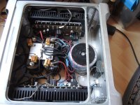
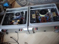
Too many wires laid out to and from the PCB.. try to use less.
I have in my amps - Rail +- wires, Ground wires, Loudspeaker only the Positive one to the PCB the second on Center/grounding this and then the Fans control ..
Try to design the Power/transistor PCB that there you don't need wires to connect the Pins.
Check out this pics so you will see the difference, and then check out my 2020 with almost only Supply in and out wires.. But that one is not finished yet so it might does not look that good. it will be in the box same as the others, in about 14 days when testing has finished. you will find in my thread about Class A.
Amps are: Class a, Ver.4 - 50Watts per channel build 2013 Single end with Constant Current Transistors Quasi Complimentary *all NPN transistors in Output * - and PID to control DC Out.
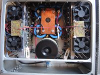
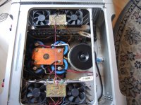
4 Fans running at approximately 450RPM / Fan
Class A Ver. 5.02 -50Watts / Channel Build September 2017 Single End with Constant Current Transistor Quasi Complimentary *all NPN transistors in Output * - and PID to control DC output & Fan Control units which will activate Fans, at the Temp of 75C and switch them of at 30C even the Amp has already been switched of beforehand.
Fan speed is 600rpm / 6 Fans and I can assure you, you will not hear the Fans
Anyway I like your build it looks good, and of course that you are using the Active Cooling sinks..
Today it's very uncomplicated to have the Fans run at speeds, so that they keep the heat exactly where the designer wants them without to be annoying loud..
If an Amp get 75C or 80C this doesn't kill the AMP otherwise my AMPS would be dead a long time ago... they run almost daily for 4 and more hours.
Nice build I like it.
Attachments
Too many wires laid out to and from the PCB.. try to use less.
My knowledge is limited, hpro - I simply use what the designer specified.
Andy
Good Work
And for that this is more than very good what you have build..
and my input is just a thought.. so please don't take it serious..
If I look back at my first build 40 years ago, then you did that one like a Masterpiece... I couldn't compare.. and this in every aspect,,
My thoughts were somewhere else, and this has nothing to do with your Build.
In my life I had two big things in my head
Never give up
Keep it simple
But anyway here is the reason for my input about to many wires.. and again this has nothing to do with your build directly, it's just my experiences in a lifetime.
Today it works and it's understandable.. in ten years when it might needs to be serviced, then it will turn out complicated, because the more parts and wires someone runs in an Amplifier or in a CAR or in a Dishwasher or whatever, the more chances are there that it fails..So easy
So take this as a compliment and not as a blaming or likewise..I would never try to offend you or put things you build down in anyway.
Good Work..
My knowledge is limited, hpro - I simply use what the designer specified.
Andy
And for that this is more than very good what you have build..
and my input is just a thought.. so please don't take it serious..
If I look back at my first build 40 years ago, then you did that one like a Masterpiece... I couldn't compare.. and this in every aspect,,
My thoughts were somewhere else, and this has nothing to do with your Build.
In my life I had two big things in my head
Never give up
Keep it simple
But anyway here is the reason for my input about to many wires.. and again this has nothing to do with your build directly, it's just my experiences in a lifetime.
Today it works and it's understandable.. in ten years when it might needs to be serviced, then it will turn out complicated, because the more parts and wires someone runs in an Amplifier or in a CAR or in a Dishwasher or whatever, the more chances are there that it fails..So easy
So take this as a compliment and not as a blaming or likewise..I would never try to offend you or put things you build down in anyway.
Good Work..
In my life I had two big things in my head
Never give up
Keep it simple
Admirable aims!
")
Today it works and it's understandable.. in ten years when it might needs to be serviced, then it will turn out complicated, because the more parts and wires someone runs in an Amplifier or in a CAR or in a Dishwasher or whatever, the more chances are there that it fails
Agreed.
So take this as a compliment and not as a blaming or likewise..I would never try to offend you or put things you build down in anyway.
Good Work..
No offence taken, hpro.
Andy
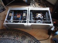
Yes MAC PRO G5
Yes that are G5 Mac Pro computer originally.. givin nice Chassis.. I buy them for about 50 - 100 CHF = Same in US$ a piece.
I also use the Heat sinks of them for my new Class A..
It's almost to the point to get it into the case..Again Mac Pro G5 Boxes
Needs a bit modeling and there we go..
Regards Chris
@jagues antoineHi Hpro,
Are those repurposed cheesegrater Mac Pro chassis ?
Nice work btw.
Cheers,
Jacques
Yes that are G5 Mac Pro computer originally.. givin nice Chassis.. I buy them for about 50 - 100 CHF = Same in US$ a piece.
I also use the Heat sinks of them for my new Class A..
It's almost to the point to get it into the case..Again Mac Pro G5 Boxes
Needs a bit modeling and there we go..
Regards Chris
Metal Film or carbon film is fine.
But you will get a different sound, right - by changing resistor type?
Perhaps you can tell me what is the difference between:
* what R124 & R126 were specified as, in the BoM - "Carbon Composition"
* and carbon film?
Thanks,
Andy
Last edited:
Carbon composition resistors have their places to be used, but they tend to drift with temperature and age and are more noisy compared to film types. When I want to use carbon resistors, I’ll go for Takman Rex carbons.
Carbon film resistors are still noisier than metal films, but I think that’s what the appeal is....added distortion. (in a good way)
Now, does it make a big difference? Probably not, it’s more of a ‘comfort’ thing
Carbon film resistors are still noisier than metal films, but I think that’s what the appeal is....added distortion. (in a good way)
Now, does it make a big difference? Probably not, it’s more of a ‘comfort’ thing
Carbon composition resistors have their places to be used, but they tend to drift with temperature and age and are more noisy compared to film types. When I want to use carbon resistors, I’ll go for Takman Rex carbons.
Carbon film resistors are still noisier than metal films, but I think that’s what the appeal is....added distortion. (in a good way)
Now, does it make a big difference? Probably not, it’s more of a ‘comfort’ thing
Very interesting, V - thanks.
Which (given the drifting values with temperature & age - plus extra noise) makes me wonder why the BoM specified 'Carbon composition resistors ' - rather than 'Carbon film resistors ', at the very least - or metal film, like elsewhere?
Hugh? X?
Andy
@AndyBut you will get a different sound, right - by changing resistor type?
Perhaps you can tell me what is the difference between:
* what R124 & R126 were specified as, in the BoM - "Carbon Composition"
* and carbon film?
Thanks,
Andy
You will not be able to hear any difference, and I doubt that you can measure it in REAL Running of the AMP..
When you exceed limits then, its sure that it will show up on the scope as well on the DVM..
If all the Amp is made with Carbon then its something else.. but not for only 2 Resistors. * this is what I understand* Anyway if possible do not change Resistor Brands and or Make within the AMP..
More likely you will get some unwanted distortion in higher levels. Carbon Resistors are not known for good high tone reproduction..
So I have to agree with Vunce.
If the BOM specified carbon composition that would be an error on my part for not catching it. It should be carbon film or metal thin film. And only at the feedback and shunt resistor positions. The carbon film has a slightly higher level of overall THD but gives a greater ratio of second harmonic vs third harmonic compared to metal thin film. Metal thin film are the safest bet and sound fine. Don’t use metal oxide thick film under any circumstance for the feedback resistor. These are sometimes the 1w or 2w “pink colored” matte finish higher power resistors. They add higher third harmonic distortion vs either carbon film or metal thin film. This was discovered in the Aksa Lender preamp thread. In SMT, metal oxide thick film is the most common cheapest surface mount resistor.
Last edited:
There's also another issue with the cart on page 1... There is the carbon thing, but in the cart both of them populate as 5% and 1/2 watt where you call for 1% 1W. I should have caught that... my ANs have both Carbon and .5W in them... looks like I have some work to do there. That's going to be a nightmare from hell to change those out.
Last edited:
Don’t worry about it. The higher wattage rating was to make sure you don’t have thermal distortion but for typical voltages at normal listening - about 8wrms the heat is negligible. You can’t buy 1% carbon film (not cheaply anyhow). You may just manually match them to achieve identical gains in each channel.
Don’t worry about it. The higher wattage rating was to make sure you don’t have thermal distortion but for typical voltages at normal listening - about 8wrms the heat is negligible. You can’t buy 1% carbon film (not cheaply anyhow). You may just manually match them to achieve identical gains in each channel.
Ya, well I'm anything, but typical..
Do we want to stay away from metal film? Also, matching would be fine, but it's still as issue because we didn't do matching to begin with and I think I did notice one side had slightly less output than the other, so they are coming out and I will get 1% or match, just sucks to have to go back in there especially how tight that board is. I think, at the very least, there should be a note and or change the cart. It might save someone else from going back in like I am.
Last edited:
I did more research on the thermal aspects.
According to D. Self - he measured (chapter 17 of his book) temperatures of his class A amp.
Assuming ambient temperature of 20 degrees, and passive cooling:
Heatsink: 67 degrees
TO-3 case: 75 degrees
Junction: 100 degrees.
For plastic transistors, junction temp gonna be higher than that (I guess 120-130 degrees).
So it seems that 75 degrees for a transistor case is acceptable, but it's not advisable to go any higher.
Ya, well I'm anything, but typical..
I think, at the very least, there should be a note and or change the cart. It might save someone else from going back in like I am.
I’ll post a note on page 1 of the GB thread where BOM is.
Don’t worry about it. The higher wattage rating was to make sure you don’t have thermal distortion but for typical voltages at normal listening - about 8wrms the heat is negligible.
But as there's more current involved in the 4R circuit ... will these resistors will get hotter?
Even if they don't ... I am not going to be replacing them!
You may just manually match them to achieve identical gains in each channel.
As I was building 4x AN PCBs, I had enough of them to match pairs within 1%. But still, when I finally finish them both, I'll measure gain in all 4 channels.
Andy
- Home
- Amplifiers
- Solid State
- Alpha Nirvana 39w 8ohm Class A Amp