I have no idea why they name it backwards 321 and make it BCE vs 123 ECB.
If you use ON Semi’s sheet you get 123 ECB.
https://www.mouser.com/datasheet/2/308/bd136-d-1190642.pdf
If you use ON Semi’s sheet you get 123 ECB.
https://www.mouser.com/datasheet/2/308/bd136-d-1190642.pdf
I have no idea why they name it backwards 321 and make it BCE vs 123 ECB.
If you use ON Semi’s sheet you get 123 ECB.
https://www.mouser.com/datasheet/2/308/bd136-d-1190642.pdf
Grrr that crap irritates me, I will have to remove them and turn them around... which is always fun.

I'm glad I asked... otherwise, when it smoked Mouser would have got an earful!
Last edited:
I bought a cheap desolder with the heat and suction built in awhile back and that little bugger is the cats rear. I hit those dudes with it and they damn near fell out of the board and the holes where perfectly clean. I spun them around and soldered them back in. It took longer for the desolder tool to warm than it did to complete the op.
Thanks again for pointing me to the correct pinout, I'm going to get Mouser on the horn, so someone else doesn't get hosed by the incorrect data sheet.
JT
Thanks again for pointing me to the correct pinout, I'm going to get Mouser on the horn, so someone else doesn't get hosed by the incorrect data sheet.
JT
Last edited:
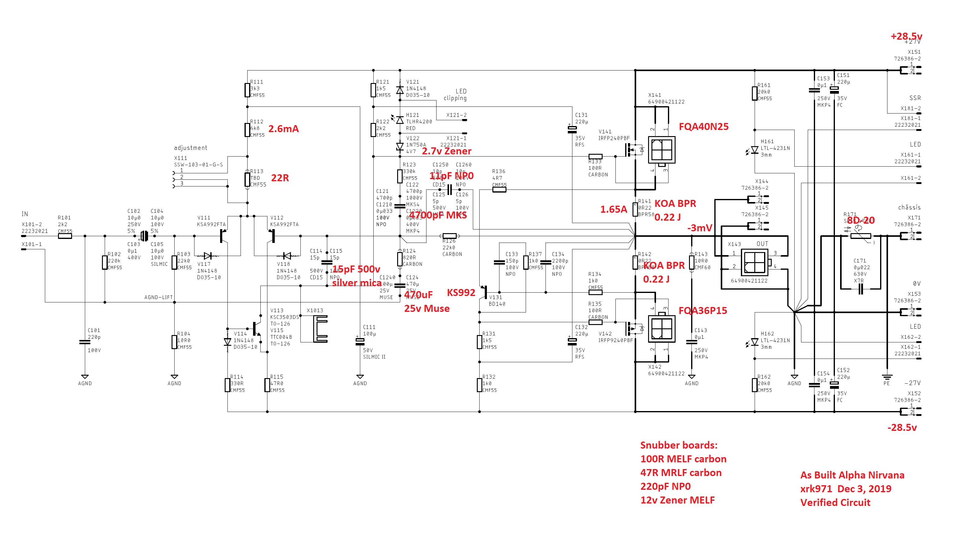
Mezzanine pins X111 - to allow placement of temp resistor for LTP.
0.033uF is C1210 and C1220 optional values
Thanks, X.
Also thanks for the 8D-20 link in the SLB thread.
Andy
The data sheet is not incorrect. Just a different notation as to which pin is pin 1.")
and pin 3
Sorry to be such a pain X, but I want to make sure on a couple things here.
Looking at the bottom of the board C171 C133 C134 have no option on top and therefore must be SMB on the bottom. Cool I get that, but then we have C126/O which is C125 from the top of the board. In your built as schematic you used 11pF I think. I get that, we don't want one of both sides of the board, or we would double the value. Cool, so use a 10-11pF on the top and leave the bottom empty. Same with C121 and C122.
Now we move on to C114 C115 which is where I get lost, there is no /O designation, on either top C114 nor bottom C115. It's the same point top to bottom and putting in another 15p would give us 30p. I do not believe that's what you want, nor did I mount one there. Was it just a type-o in the lack of the /O or did I miss something.
Thanks for all your help X.
JT
Attachments
Last edited:
Hi ThompsonTech,
The layout by JPS64 has a lot of options for folks who like to use SMT NP0/C0G caps vs TH silver mica caps where the smaller critical audio compensation caps are placed. You can tell it is critical when the schematic shows NP0/C0G or Silver Mica. Do not use both, use what you like. Personally, I like NP0/C0G. But, I have been told sonics of silver mica is better. I use whatever I have on hand and I happen to have the silver mica's. If there is a SMT pad on same spot as through hole and designation is same first few digits but either incremented by 1 (C114/115) or an extra zero is added, it is alternate configuration. In some rare cases where you need say 30pF but all you have is 15pF silver mica and 15pF NP0/C0G SMT, then use both TH and SMT pads!
General rule is go with what the schematic shows, and if you see that I only mark red designation once for a place that shows two caps, pick the one.
Hope that helps.
Last edited:

....
I wondered if for my situation (explained below) a 22v transformer would be acceptable, if not preferable. Hugh’s design called for +/- 27 vdc. Based on X’s build and use of SLB PSU I believe he gets 28.5 vdc in practice.
Question 1: X, for the record, what is your wall power AC voltage? Mine is consistently 125-128 VAC. So, if X’s utility provides around 125Vac, I estimate that I should get about +/- 26 vdc from a 22 vac transformer also using a SLB PSU.
Question 2: Is a supply of +/- 26 vdc acceptable for the AN, or is +/- 28.5 vdc preferable? I do not mind loosing a few watts output power, and will appreciate reducing the heatsink load a bit.
Question 3: Will a 500VA transformer be sufficient for my two channel build? Unfortunately Antek does not offer a 22 VAC transformer in VA rating >500 (AN-5222). Or should I just get the AN-6424 even though I might end up with a supply of +/-29 or so?
Your discussion and input shall be appreciated.
I got a reply from X on his wall voltage (thanks much), but nothing else.
I shall appreciate more help with my specific questions. I can imagine these questions are relevant to many builders regarding their power supplies. Any comments?
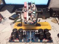
Nice work!
Computer desk doubles as PCB assembly table
Yes it does... that's for many reasons, not the least of which is to be able to reach out to you when needed!
I got a reply from X on his wall voltage (thanks much), but nothing else.
I shall appreciate more help with my specific questions. I can imagine these questions are relevant to many builders regarding their power supplies. Any comments?
+/-26.5v is fine if you don’t mind losing peak power. Any lower then you need to adjust resistor that sets bias current in LTP to keep at near 2.6mA.
For Antek in Class A, because of voltage sag at high currents, I would always “buy up” to next size. 29v rails are ok as long as your heat sink can take it. Size VA rating at 3x nominal power to ensure minimal voltage sag. Get the 6424.
Thanks! I would rather have a few watts less output than many more watts heat, so I will aim for the design optimal +/- 27 Vdc supply and look into adjusting, if necessary, the LTP bias current. Which resistors would that involve?
I think R112 but will let Hugh answer that. You might try looking at the schematic for the 4R version as it has lower voltage rails and see where difference is. At 27v I wouldn’t worry. But 24v or lower then need to adjust.
I thought the “standard AN 39 watt” design specially called for +/-27 Vdc, and your practical +/-28.5 Vdc was a compromise. No?
Last edited:
- Home
- Amplifiers
- Solid State
- Alpha Nirvana 39w 8ohm Class A Amp