There are dip switches and pots that let you adjust the speed and the temp threshold for speed up. You want it as slow as possible while still keeping things sufficiently cool. It’s probably closer to 500rpm is my guess but we go by noise and we aim for silent. You can’t tell the fans are on type silent.
4 Ohm Speaker Version?
Rather than trawl through the topic of 1942 posts can anyone point me to the info. regarding the 4 Ohm version? I was born in 1942 even using the search facility I can see that to find this stuff could take all my remaining time!!
Many thanks for help.
Rather than trawl through the topic of 1942 posts can anyone point me to the info. regarding the 4 Ohm version? I was born in 1942 even using the search facility I can see that to find this stuff could take all my remaining time!!
Many thanks for help.
Brianco,
I found everything through links on the first post of this thread.
Here is AndyR's BOM compilation for 4 ohm and 8 ohm (post 502):
https://www.diyaudio.com/forums/sol...irvana-39w-8ohm-class-amp-51.html#post6021334
Schematic and some relevant discussion here where Andy clarifies some details (posts 483-490):
Alpha Nirvana 39w 8ohm Class A Amp
A detailed post of Oscope measurements member AndyR made with his 4 ohm build (post 1287):
https://www.diyaudio.com/forums/sol...rvana-39w-8ohm-class-amp-129.html#post6217881
Best,
Anand.
Last edited:
Vunce, X, others,
So my CPU coolers are all 100mm high x 95mm wide. Are there clips supplied with these Noctua fans , or are mounting bolts around the OD of the fan used, or are folks mounting the fan to the chassis a suitable distance away from the heatsink?
I tried to get some closeup pics of mounting procedures, but hard to find. I am thinking the A9 model that Vunce uses should work fine for my needs, if I can mount it properly.
Suggestions or pics to help out")
MM
So my CPU coolers are all 100mm high x 95mm wide. Are there clips supplied with these Noctua fans , or are mounting bolts around the OD of the fan used, or are folks mounting the fan to the chassis a suitable distance away from the heatsink?
I tried to get some closeup pics of mounting procedures, but hard to find. I am thinking the A9 model that Vunce uses should work fine for my needs, if I can mount it properly.
Suggestions or pics to help out
MM
I use single strand of CAT5 wire to wrap around the cpu cooler fins and attach to the fan mounting holes. Use a wire around the top and bottom so the fan is supported well. The silicone corners on the Noctua fan help dampen any vibration. The fan/cooler combo work best when the fan is right up to the aluminum fins, no space between.
Vunce, X, others,
So my CPU coolers are all 100mm high x 95mm wide. Are there clips supplied with these Noctua fans , or are mounting bolts around the OD of the fan used, or are folks mounting the fan to the chassis a suitable distance away from the heatsink?
I tried to get some closeup pics of mounting procedures, but hard to find. I am thinking the A9 model that Vunce uses should work fine for my needs, if I can mount it properly.
Suggestions or pics to help out
MM
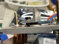
My slim-line Noctua fans are mounted to the case's base panel (above a hole cut out for airflow), using the rubber fixers supplied.
The CPU coolers are mounted on a bracket made from 6mm aluminium, bent into a right-angle and also fixed to the base panel. Thus the cooler fins sit vertically.
Andy
Just a little update... Both channels are up but I'm dealing with my transformer rather annoying humming sound at the moment. I've posted on the SLB thread, but nothing to do with the SLB itself, just the transformer. It does not prevent me from testing the amplifier though, as with the cover on, I can still hear it, but it's not as bad.
Heatsinks are at 47-50 Celcius and holding after 45 minutes, which should be fine.
Do
Heatsinks are at 47-50 Celcius and holding after 45 minutes, which should be fine.
Do
Just a little update... Both channels are up but I'm dealing with my transformer rather annoying humming sound at the moment. I've posted on the SLB thread, but nothing to do with the SLB itself, just the transformer. It does not prevent me from testing the amplifier though, as with the cover on, I can still hear it, but it's not as bad.
Do
DC on the mains? As I understand it ... the larger the VA rating of a transformer ... the more likely it is to hum as a result of there being DC on the mains. And yours is 800VA!
Heatsinks are at 47-50 Celcius and holding after 45 minutes, which should be fine.
Purrfect!!
Andy
Hi Do,
Sometimes there is DC on the AC mains. This can unbalance a transformer and generate hum.
Try measuring the mains for DC. If it is more than 200mV I would suggest using an AC bridge after the mains plug before the transformer, and a couple of large 22000uF caps across the bridge (2 x 35A) to remove any DC.
Hugh
Hi Andy, Hugh,
The troubleshooting I’ve done is on the SLB thread. I’ve already checked for DC on the mains and I’m at a comfortable 2mV DC, so no issues.
I’ll be testing the full amplifier shortly. The transformer humming does not get to the speakers, so it is just the annoying humming. Please see SLB thread for all troubleshooting done. I’m at a point where I’ve contacted Toroidy.
Thanks
Do
CPU cooling
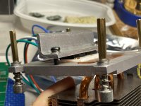
A couple of questions to builders that have used cpu cooling techniques. I have some copper pieces that are 1/4" thick and fit nicely on the cooler. I have attached a couple of pics for illustrative purposes.


My plan is to drill / tap 2 or 3 x 1/4" holes on each end of the top of the cooler and attach the copper plate. The white dots represent the holes. Washers will be used for distribution of force applied to hold the Mfets in place.
Question: Do you think that there will be enough hold down force applied to the Mfets with what I am planning?
Thanks,
MM
A couple of questions to builders that have used cpu cooling techniques. I have some copper pieces that are 1/4" thick and fit nicely on the cooler. I have attached a couple of pics for illustrative purposes.
My plan is to drill / tap 2 or 3 x 1/4" holes on each end of the top of the cooler and attach the copper plate. The white dots represent the holes. Washers will be used for distribution of force applied to hold the Mfets in place.
Question: Do you think that there will be enough hold down force applied to the Mfets with what I am planning?
Thanks,
MM
Heat transfer to the sink pad
Hi Myles,
I think this will do it nicely.
Transfer of heat to the CPU heat pad depends on the flatness of the metals, heat paste used between them, and force holding them together. Since your Cu block appears to have been drawn very flat in manufacturing, the CPU heat pad is almost optically flat, and you do not need to use non-conductive paste (use some with silver if you can find it) the transfer will be excellent.
Cu is great for this job. Look at some of the watt per metre-Kelvin conductivity from Wikipedia:
Aluminium 237
Alumina 30
Beryllia 209-330
Boron arsenide 1300
Copper (pure) 401
Diamond 1000
Fiberglass or foam-glass 0.045
Polyurethane foam 0.03
Expanded polystyrene 0.033–0.046
Manganese 7.810 Lowest thermal conductivity of any pure metal.
Water 0.5918
NOTE: Don't overtighten the six bolts, they could easily bend the Cu plate, destroying heat transfer.
Hugh
Last edited:
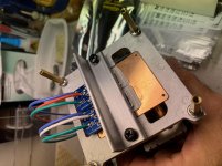
Copper is not easy to drill and tap. Aluminum is much easier to work with and the “clamp” is not the important part dissipating the heat. This is the method I use. Aluminum angle will not bend or flex when clamping the mosfets to the CPU copper pad. There is also no chance of shorting mosfet legs being trapped under the clamp
Attachments
Thanks Hugh and Vunce,
We are thinking along the same lines here. I would only tap the aluminum, as you have Vunce. These pieces of copper are heavy, and will not need much force to be an effective clamp.
Vunce, I see your point about shorting out the Mfet legs. I can cut the copper along the length, and make 2 clamps out of one piece of copper. Then, clamp as you have covering the Mfet body, reducing chance of short. Also only 2 bolts as you show. I have all this copper and would like to use it.
Vunce you got me stumped, "It looks like you have 3 layers of some sort of thermal paste / pads between the transistor and the heatsink?.
Can I use normal thermal heatsink paste, I just bought a large tube of Noctua thermal paste.
MM
The devices (mosfets, BJTs, etc..) need to be insulated from the copper pad to avoid shorting, I use alumina ceramic insulators between the mosfet and cpu cooler.
100PCS Alumina Ceramic Insulating Sheet TO-247 MOS Transistor IGBT Cooling Pad | eBay
Cpu copper pad —> thermal paste —> insulator —> thermal paste —> mosfet —> aluminum clamping bar.
100PCS Alumina Ceramic Insulating Sheet TO-247 MOS Transistor IGBT Cooling Pad | eBay
Cpu copper pad —> thermal paste —> insulator —> thermal paste —> mosfet —> aluminum clamping bar.
- Home
- Amplifiers
- Solid State
- Alpha Nirvana 39w 8ohm Class A Amp