Legaleze has nothing with my aversion to the use of “Nirvana” in a hifi product. And A Nirvana/AN is often used to describe Audio Nirvana drivers.
Lots of things can be trade-marked. Not a really important, name i would have choosen give its bad conotations to me. It isn’t important, what is, is that we have another DIY Class A amp from a brilliant designer.
dave
Lots of things can be trade-marked. Not a really important, name i would have choosen give its bad conotations to me. It isn’t important, what is, is that we have another DIY Class A amp from a brilliant designer.
dave
Haha, a musician named Alpha with a Song/Album called Nirvana. Who would have thunk?

Member
Joined 2009
Paid Member
All correct, Bigun........
One thing; the active CCS is concertina, the voltage across the two sources resistors will remain constant at 0.65V, but the two resistors will pass conjugate currents which will always sum to 3.4A. The two resistors are identical so that the see-saw action is completely symmetrical.
HD
The original Aleph current source allows you to tweak how much of the load induced current variations are passed back to the amplifier and I remember reading that a symmetrical split was not always the preference - in this SEPP/SRPP style you can also tweak the values of the two resistors so that it’s not symmetrical, if you happen to prefer it that way... of course you will trade off some of the efficiency if you do that.
Dave, what are you babbling on about the name for?
 many people are very happy with their audio nirvana drivers, including myself, so there are no negative connotations
Last edited:
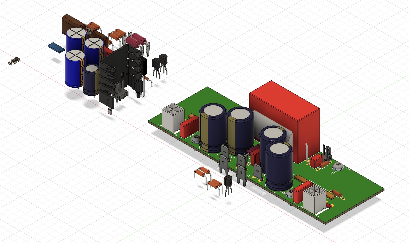
Warning with PCB.Ahh, to see JPS64’s mastery of the art of layout. Work in progress, but the PCB will have same footprint as Alpha 20 and be UMS compatible and have option for flying lead Molex Minifit Jr connectors.
The two 0.22 ohms resistors must imperatively be non inductive , I used ordinary 5w the circuit oscillate. They must be physically parallel very near to each other so that there is the least distance for the Q4 transistor to capture the current sense . I don't see the outputs , the source of IRFP9240 must be just on the 0.22 ohms . This makes the P MOSFET ,Q4 and the two resistors must make a single block . You are dealing with a closed loop circuit of 10Mhz.
Last edited:
many people are very happy with their audio nirvana drivers
True. But i have yet to hear a set that are worthy or in one case worthy of the price. I have not heard yours.
dave
....isn’t the theoretical maximum efficiency of a Class A amp 25%?..
50% for straight push-pull or choke/transformer coupled.
25% for CSS loaded.
8% for resistor loaded.
Pentode tubes will approach 80% of these values -- a 12W 6V6 SE will do 5 Watts out. Triodes at "sane" conditions rarely get over 25% (half of theory) because they are so lossy.
Transistors can do considerable better than tubes. An old book shows 48% in SE. 45% would be a lot more typical, with exact loading, and not being too concerned about THD. The MoFo amp in Pass forum seems to give 38%-42% at very low THD if the idle condition is well-considered.
The datasheet doesn't speak about non inductive character. The leads must be magnetic, if you have one , check it with a magnet . BPR56 is noniductive and is high magnetic with hard leads for high currents . The ERX advocates low heat transmission to PCB , it means the leads are low heat conducting, hence no iron content .I have specified Panasonic ERX 3w metal thin film source resistors. That’s what is always specified for this part due to low inductance and low distortion.
Last edited:
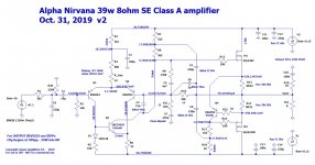
Here is the Alpha Nirvana v2 schematic with Hugh's latest tweaks:

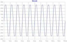
Here is the behavior at clipping - notice how symmetric it is:

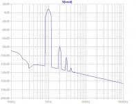
Here is the FFT for 8Vpp into 8ohms:
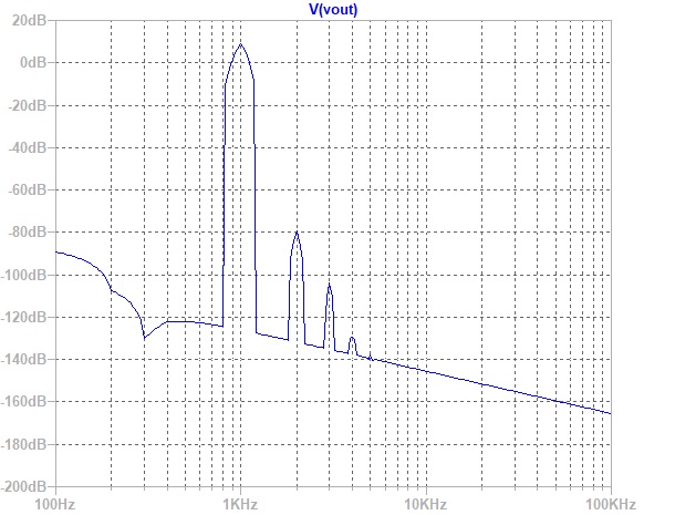
Here are the distortion components with 0.0039% THD:
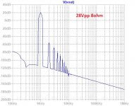
And here is FFT for 28Vpp into 8ohms (12.5w):
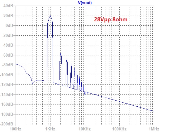
And here are the distortion components for 0.016% THD:
Here is the behavior at clipping - notice how symmetric it is:
Here is the FFT for 8Vpp into 8ohms:
Here are the distortion components with 0.0039% THD:
Code:
Harmonic	Frequency	 Fourier 	Normalized	 Phase  	Normalized
 Number 	  [Hz]   	Component	 Component	[degree]	Phase [deg]
    1   	1.000e+03	3.937e+00	1.000e+00	   -0.68°	    0.00°
    2   	2.000e+03	1.538e-04	3.906e-05	 -113.08°	 -112.40°
    3   	3.000e+03	8.049e-06	2.045e-06	   56.41°	   57.09°
    4   	4.000e+03	1.027e-06	2.608e-07	  164.55°	  165.23°
    5   	5.000e+03	1.262e-06	3.207e-07	 -177.53°	 -176.85°
    6   	6.000e+03	1.038e-06	2.637e-07	  179.93°	  180.61°
    7   	7.000e+03	8.854e-07	2.249e-07	  179.88°	  180.56°
    8   	8.000e+03	7.748e-07	1.968e-07	  179.92°	  180.60°
    9   	9.000e+03	6.887e-07	1.749e-07	  179.93°	  180.61°
   10   	1.000e+04	6.198e-07	1.574e-07	  179.94°	  180.62°
   11   	1.100e+04	5.635e-07	1.431e-07	  179.94°	  180.63°
   12   	1.200e+04	5.165e-07	1.312e-07	  179.95°	  180.63°
   13   	1.300e+04	4.768e-07	1.211e-07	  179.95°	  180.63°
   14   	1.400e+04	4.427e-07	1.125e-07	  179.95°	  180.64°
   15   	1.500e+04	4.132e-07	1.050e-07	  179.96°	  180.64°
Total Harmonic Distortion: 0.003912%(0.004251%)
And here is FFT for 28Vpp into 8ohms (12.5w):
And here are the distortion components for 0.016% THD:
Code:
Harmonic	Frequency	 Fourier 	Normalized	 Phase  	Normalized
 Number 	  [Hz]   	Component	 Component	[degree]	Phase [deg]
    1   	1.000e+03	1.417e+01	1.000e+00	   -0.68°	    0.00°
    2   	2.000e+03	2.278e-03	1.608e-04	 -115.76°	 -115.08°
    3   	3.000e+03	5.799e-04	4.092e-05	   51.25°	   51.93°
    4   	4.000e+03	1.615e-04	1.139e-05	   20.66°	   21.34°
    5   	5.000e+03	6.764e-05	4.773e-06	 -110.87°	 -110.19°
    6   	6.000e+03	2.623e-05	1.851e-06	 -177.51°	 -176.82°
    7   	7.000e+03	8.719e-06	6.152e-07	   98.94°	   99.62°
    8   	8.000e+03	3.366e-07	2.375e-08	  -37.39°	  -36.70°
    9   	9.000e+03	2.908e-06	2.052e-07	 -157.53°	 -156.85°
   10   	1.000e+04	2.602e-06	1.836e-07	  178.74°	  179.43°
   11   	1.100e+04	1.990e-06	1.404e-07	  176.05°	  176.73°
   12   	1.200e+04	1.803e-06	1.272e-07	 -179.77°	 -179.08°
   13   	1.300e+04	1.709e-06	1.206e-07	 -179.55°	 -178.87°
   14   	1.400e+04	1.588e-06	1.121e-07	  179.91°	  180.60°
   15   	1.500e+04	1.477e-06	1.042e-07	  179.90°	  180.58°
Total Harmonic Distortion: 0.016635%(0.016717%)
Attachments
PRR,
Thank you for the useful Class A information.
KK,
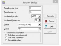
Here is the LT command line:
.options method=gear
.options numdgt=7
.param freq=1k
.param numcyc=10
.param dlycyc=10
.param FFT=2**16
.param simtime=numcyc/Freq+dlytime
.param dlytime=dlycyc/Freq
.param timestep=(simtime-dlytime)/FFT
.four {freq}15 8 V(Vout)
.four {freq} 4 8 V(Vout)
Perhaps you can suggest how to change this to delay the measurements for ten cycles?
HD
Thank you for the useful Class A information.
KK,
Here is the LT command line:
.options method=gear
.options numdgt=7
.param freq=1k
.param numcyc=10
.param dlycyc=10
.param FFT=2**16
.param simtime=numcyc/Freq+dlytime
.param dlytime=dlycyc/Freq
.param timestep=(simtime-dlytime)/FFT
.four {freq}15 8 V(Vout)
.four {freq} 4 8 V(Vout)
Perhaps you can suggest how to change this to delay the measurements for ten cycles?
HD
Last edited:
You could brute force it by running the sim for a much longer time. These sims take about 5 seconds and are going to get the profile shape and THD probably within 10% of final answer. Extending the duration by 10x or circa 1min sim run probably works but not pleasant to do.
It’s might have something to do with delay-cycles directive.
It’s might have something to do with delay-cycles directive.
.param numcyc=10
.param dlycyc=10
Last edited:
- Home
- Amplifiers
- Solid State
- Alpha Nirvana 39w 8ohm Class A Amp