R111-3K , R112-5K , R113-1K pot , R121-820R ,
R122-1K2 , R132-820R , R161-14K7 , R162-14k7
So you don't use the above values but the original Andy's 4R version except R141_142 at 0.15Ω.
Hi Andy
Can i ask you something ? once you make the version 4R same story here
...
Which is the bias Ampere that you set your amp?
Did you put also the capacitor C134 2200pf?
I see your construction in a box how about the temperatures ?
Kalimera, Nikos.
I used R15/R16 (as named in Hugh's 4R schematic - these are R141/R142 in the "as built 8R schematic") at 0.12R - which was designed to give 3a bias.
C134 (in the "as built 8R schematic") doesn't appear in Hugh's 4R schematic - but is obviously on the PCB. So I suspect I did put C134 in - and it would've been 2200pF, as per the "as built 8R schematic".
Yes, the 3a bias current - whilst it enables the 4R circuit to be stable into 2 ohms ... does create a lot of heat.
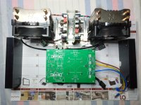
 I originally had each pair of output devices bolted to a CPU cooler - with a fan underneath it (and a hole in the base of the case). This kept the devices to about 60 deg ... but, even with the 12v fans being run at a lower voltage, I heard too much fan noise (not surprising, as there were 4 fans!).
So I re-housed the amps in a 5RU Modushop case, having 300 long & 210 high heatsinks; these don't cool the output devices quite as well as the fan configuration did - so I am about to change R15/R16 to 0.15R (which should reduce the heat output - and the device temperatures - slightly).
Κalispera my friend Andy.So I re-housed the amps in a 5RU Modushop case, having 300 long & 210 high heatsinks; these don't cool the output devices quite as well as the fan configuration did - so I am about to change R15/R16 to 0.15R (which should reduce the heat output - and the device temperatures - slightly)
Thank you very much for the construction details.
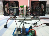
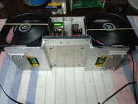
I have seen your construction.....however, due to the height of your box, you have placed the active fan not vertically but horizontally and the temperature is trapped in the radiator. These active fan work much better when they are vertical. I have tried as I mentioned above with classic heatsinks, but the heat dissipation is much worse. The problem is in the heat that is trapped above the body of the mosfet, and for that you also need cooling in the housing, see my photo.
In this way I have achieved 41 degrees Celsius at 3,188 A.
Attachments

Am in the process of replacing the current 0.12R R141/142 with 0.15R.
One amp is done - so, seeing how 'topless' shots are in vogue atm, I thought I would post one:

The case is a 5RU Modushop 'Dissipante'. Transformers are Aus made, from Tortech, spkr terminals are EIZZ and input RCAs are Vampire PCB2FA (unfortunately, no longer available ).
One amp is done - so, seeing how 'topless' shots are in vogue atm, I thought I would post one:
The case is a 5RU Modushop 'Dissipante'. Transformers are Aus made, from Tortech, spkr terminals are EIZZ and input RCAs are Vampire PCB2FA (unfortunately, no longer available
).Alas - I now need some smart suggestions from people who can help me figure out what is wrong!
After replacing R141/R142 in both channels, I reassembled the amp and switched it on - and nothing smoked! Yay!
Put a 1kHz signal through the R channel - and looked at the output on my 'scope ... a lovely clean sine wave. Then I put a 4R/50w load across the R channel's spkr terminals - the nice sine wave continued.
So the R channel is AOK.
Repeated this with the L channel:
* without the spkr load resistor connected - there was no problem; ie. a smooth sine wave on the 'scope.
* but when I connected the 4R resistive load ... the smooth sine wave on the scope continued - but I began to hear a very high-pitched whine (maybe 8 -10kHz?). So I'm thinking ... something must be causing an oscillation in the L channel - but only when the spkr load resistor is connected. But whereabouts in the amp circuit can this be?
Andy
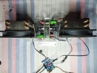
First of all I would look at my mosfet connections....I don't trust that type of Molex type connections....I have also seen point to point connections on to ONE mosfet? (filter 47Ω+220pf) ? Blurry image... look for loose connection......etc reduce mosfets wires .. ..increase the resistors gates ...all these with gen and scope..
First of all I would look at my mosfet connections....I don't trust that type of Molex type connections....I have also seen point to point connections on to ONE mosfet? (filter 47Ω+220pf) ? Blurry image... look for loose connection......etc reduce mosfets wires .. ..increase the resistors gates ...all these with gen and scope..
Last edited:
Andy,
Nikos is on the right path I suspect. I also see a point to point method of attaching the snubber circuit for the Mosfets…in my honest opinion, the pcb that X sells is a much more optimized option with the snubber circuit, gate stopper, etc…all intrinsically attached to the respective pcbs. Long leads from the main pcb to the Mosfets is always a risk for possible oscillation unless a properly designed and implemented snubber circuit is included.
Good luck!
Best,
Anand.
Little progress about box setup about 16.5cm high.
https://vimeo.com/936791585?share=copy
https://vimeo.com/936791585?share=copy
Attachments
Thanks for the suggestions, guys:
I also hate those Molex connections with a passion - but, having soldered the pins to the PCB ... I think they're gonna be very difficult to remove.
Anybody have any suggestions as to the best way of going about it?
Also, if it is oscillation ... why am I seeing a nice clean 1kHz sine wave on my 'scope screen? Surely, I should see the oscillation on the screen?
Maybe I need to try a 10kHz input signal?
And why does it only happen when I have a spkr load connected - ie. I'm drawing current?
Andy
Andy
First of all I would look at my mosfet connections....I don't trust that type of Molex type connections....I have also seen point to point connections on to ONE mosfet? (filter 47Ω+220pf) ? Blurry image... look for loose connection......etc reduce mosfets wires .. ..increase the resistors gates ...all these with gen and scope..
Andy,
Nikos is on the right path I suspect. I also see a point to point method of attaching the snubber circuit for the Mosfets…in my honest opinion, the pcb that X sells is a much more optimized option with the snubber circuit, gate stopper, etc…all intrinsically attached to the respective pcbs. Long leads from the main pcb to the Mosfets is always a risk for possible oscillation unless a properly designed and implemented snubber circuit is included.
I also hate those Molex connections with a passion - but, having soldered the pins to the PCB ... I think they're gonna be very difficult to remove.
Anybody have any suggestions as to the best way of going about it?
Also, if it is oscillation ... why am I seeing a nice clean 1kHz sine wave on my 'scope screen? Surely, I should see the oscillation on the screen?
Maybe I need to try a 10kHz input signal?
And why does it only happen when I have a spkr load connected - ie. I'm drawing current?
Andy
Andy
First of all I would look at my mosfet connections....I don't trust that type of Molex type connections....I have also seen point to point connections on to ONE mosfet? (filter 47Ω+220pf) ? Blurry image... look for loose connection......etc reduce mosfets wires .. ..increase the resistors gates ...all these with gen and scope..
How very interesting, Nikos; the email which diyAudio sent me, alerting me that you had made a post, was in Greek - yet the post appeared in diyAudio, in English!
Do you actually post in Greek (and diyAudio translates it for you)?
Hi Andy
Doesn't translate Diyaudio for me.....
English is not my native language...I edited and corrected it in English.
I had previously done a copy paste from Google translate to be sure that I am not writing them wrong....
Aah, OK.
(Unfortunately, my Greek is only at the stage where I can read what you wrote (in Greek) ... but I can't understand what I'm reading.
)Hah - problem #1 (hearing a high-pitched whine on the L channel, with a 4ohm load connected) ... seems to have gone away. Amp is now silent (both channels). Verry strange - but welcome!
But problem #2 has now appeared; this is ... the red clipping LEDs never go on (both channels)!
This is with the 4-ohm/50w load connected - and a (top-) clipped sine wave showing on the 'scope screen. The red LED is supposed to come on a couple of volts lower than the clipping voltage - at least, that's what happened when I did the "power output" testing, when I first got my amps working, in 2021.
I've tested both LEDs with my Atlas DCA75 - and they both show as 'working'. And I have the LEDs connected the right way, on the PCBs (cathode on the outside of the PCB).
Can anyone offer any suggestions as to why the LEDs are no longer functioning as clip indicators - iow ... what components should I test, to make sure they're not blown?
(Could it be anything to do with the fact that I have changed the NPN Mosfet (FQA40N25) to a Darlington (2SD2560), on Hugh's suggestion ... for added 'slam' and impact?)
- Home
- Amplifiers
- Solid State
- Alpha Nirvana 39w 8ohm Class A Amp