Or 10U x 350mm heatsinks! 🥹
But if 2A then only 128W - a bit more manageable.
Latest measurements by Keantoken on commercial A40 amp shows distortion vs power behaving nicely.

Here are components vs frequency at relatively high 30W:

Always second harmonic dominant and descending higher orders. Just as it should be.
But if 2A then only 128W - a bit more manageable.
Latest measurements by Keantoken on commercial A40 amp shows distortion vs power behaving nicely.
Here are components vs frequency at relatively high 30W:
Always second harmonic dominant and descending higher orders. Just as it should be.

Im okey thank you.Hi Nikos,
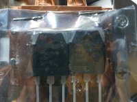
I only have one FQA35P15 left, but I have four IXTH48P20, which are replacements for FQA36P15.
I could give two of them away if it helps.
A member covered me with a pair of mosfet.
Merci beaucoup!!!.
From a capacitance standpoint, you should be fine. But the resistor values imho are too large, you will lose a lot of voltage off of your rectified rails. Remember this is not a Class AB build, it’s a Class A build, where a constant bias current of at least 2A (since this is a 4 ohm build) is going through these resistors. So you lose 0.4V at R1, 1V at R2, and 1V at R3 = 2.5V. This will raise the impedance of the supply which can affect bass response. The resistors will also need to be higher wattage, i.e. P = I^2*R. So R1 will need to absorb 0.88 watts, R2 will need to absorb about 2 watts and R3 will need to absorb 2 watts. You will need to upsize those resistors by 3 times that value, so 3 watts, 6 watts and 6 watts because they will get very warm and will be prone to fail if undersized in power. I would not recommend your supply at all.
Please consider the schema published by Randy T elsewhere on diyaudio and also his build guide:
https://www.google.com/url?sa=t&rct=j&q=&esrc=s&source=web&cd=&ved=2ahUKEwjUu_Wi_LKEAxXsMlkFHSABBv0QFnoECBAQAQ&url=https://www.diyaudio.com/community/attachments/v8-crcrc-build-guide-1-0b-pdf.1157033/&usg=AOvVaw2bfkbGwUfmmG3v8WvYtNce&opi=89978449
You can use one per channel and point to point wire it, design your own pcb or just purchase the boards from Randy himself (easiest and most optimized option!). Notice his design is CCRCRC which has it’s advantages. This power supply has been used numerous times by Aleph 60 and Aleph 2 builders and is pretty much bullet proof. It also includes the bleeder resistors so the capacitors don’t hold charge at switch off. It also includes a simple softstart using thermistors and also a ground loop breaker (using a thermistor). In the future, if you want to you can replace the rectifier portion with active rectification if you want since the rectifier boards are completely separate from the main PS board.
Best,
Anand.
Last edited:
Knauf,
Anand has put it very well; caps are fine, I'd suggest reducing all the resistors to 0.15R, all rated at 3W.
With a 4R load the 2A quiescent (ideally it should be 3A actually) each resistor will dissipate 0.6W, and 3A would dissipate 1.35W. So 3W will give a moderate temperature rise and long life.
Be aware that more power supply capacitance will draw higher surge currents from the transformer; there is a balanced here. My thoughts are that about 30mF is about right for each rail on a 40W Class A.
HD
Be aware that more power supply capacitance will draw higher surge currents from the transformer; there is a balanced here.
Yes. It’s one of the reasons I use softstarts in all my builds that use a transformer of 300VA or more.
Tom Christiansen of Neurochrome Audio has written a rather comprehensive summary of all the factors involved in designing a softstart. An important factor is the energy storage of each capacitor in the powersupply. For the newbie diy builder (not Hugh of course!) It can be calculated rather easily…E =0.5 * C * V * V; where C is the capacitance in farads, and V is the DC rectified voltage. That’s the storage of EACH capacitor which you have to add together so as to understand the energy load imposed on the transformer! The peak currents these transformers endure are pretty amazing, and that happens every time you switch the amplifier on!
This huge current surge repeatedly stresses the primary of the toroid and over time the enamel and insulation of the primary breaks down eventually short circuiting to the core. At this time transformer demise and failure occurs.
The energy storage of each capacitor in your power supply becomes important in selecting an inrush thermistor that can withstand that joule rating. The maximum (for example) of the ubiquitous CL-60 is only 36 joules. That’s usually not my first choice unless low currents and low rectified dc voltages are involved (see the equation above for why). My first choice is typically Ametherm SL22-20007 which has a rating of 125 joules.
Thankfully, these thermistors have to endure this surge for only a short period of time (less than 1 second). In the previous example where I mentioned R.Thatcher’s V8 power supply, I would substitute the thermistor with at least a 125J rating since the energy to magnetize the core of the transformer has to also be taken into consideration. For example the energy to magnetize a 400VA core is just under 20 joules.
For example if one were to use a V8 power supply for EACH channel, you have (16) 22,000uf capacitors in the stereo amplifier. Assuming dc rails at +/- 20V (for example), then each capacitor would hold 4.4J of energy. 16 of them would be 70.4J of energy. And if you were using two 400VA transformers, you would add 40 more joules. The total is 110J. Thankfully that’s not super high because the voltage rails are only +/- 20V. Change that to +/- 28V as is seen in the 8 ohm Alpha Nirvana and the energy storage is much much higher since voltage is squared in the equation. Of course, the dc voltage only holds true if the mains stays at the nominal level. If your mains varies, so will your dc voltage 😉.
I’ve rambled on enough but I think y’all get the idea!
Best,
Anand.
Last edited:
Hi ...
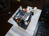
I m still collecting parts for this amp AN39.
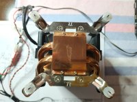
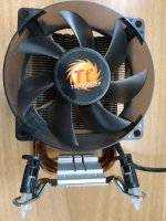
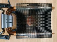
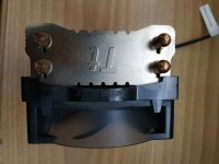
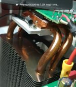
I found this ... heatsink fan 90cm pwm THERMALTAKE Silent 1156 .What do you think its good for cooling?
I m still collecting parts for this amp AN39.
I found this ... heatsink fan 90cm pwm THERMALTAKE Silent 1156 .What do you think its good for cooling?
Attachments
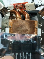
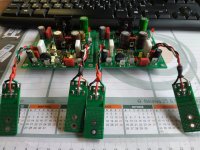
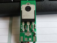
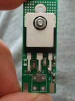
Μy boards arrived.... everything good.
Voltage 21.50DC-21.80DC
On 3.3k 8.30V-8.50V
On 0.22Ω about 353mv ~1.6A
Offset about -2.8 -3.2mv with pot 200Ω and 22Ω νalue...
I don't listening music yet.
Voltage 21.50DC-21.80DC
On 3.3k 8.30V-8.50V
On 0.22Ω about 353mv ~1.6A
Offset about -2.8 -3.2mv with pot 200Ω and 22Ω νalue...
I don't listening music yet.
Attachments
Last edited:
Ηi James my friend how are you?How are your temps?
My temp at 1.6A from first initial tests with active fan Thermatake PWM by microcontroller activated initial at 40C rise up to 48C down then until the deactivate the fan at 38C cycles again and again. the temp on body FQA about 52-58.
Hi, in the end I am going to mount the 20w//8ohms version (20V rails). I will use it to feed the mid and treble part (92db/w) on a 3 way speaker.
This is the schematic that Hugh designed and offered to this forum...thanks!

You can see some changes from the original version. To make a little memory I copy and paste the explanations given by Hugh himself:
"This amp uses 20V rails, and performance is not as good as the 27V rails and about half the power. But it's essentially the same amplifier with very similar harmonic profile. Interestingly at 20KHz and 12.5W//8R the H2 is at -45dB, which is almost identical to a tube like 6SL7 operating at B+ of 340V and 1.6mA plate current. It clips at just under 21W, and quiescent is 1.32A. Front end is slightly changed; R4 could be a 2k pot to set offset. Quiescent is set by the two 0.27R resistors in the sources of the outputs, which each dissipate an easy 25.5W."
" you can replace the blue led with a 2.7V zener".
There are things that I understand and things that I don't (in blue the 20w version).

I will explain what I think I understand:
R111 is replaced by 1k75 ohms
R112 for 5k6 ohms
R113 could be a 200 ohms adjustable resistor for dc offset adjustment.
R141 for 0.27 ohms
R142 by 0.27 ohms
-My doubts:
Set 1 (in blue)- R121 and R122 (39w) are different values to R8 and R9 (20w).
Set 2- Led 2 blue or zener diode 2,7v reverse biased than the original version?
Can I follow the same order as in the original circuit (39w) reversing only the zener diode?
Sets 3 and 4- shouldn't I change the value of resistors R161 and R162?
Thanks in advance
This is the schematic that Hugh designed and offered to this forum...thanks!
You can see some changes from the original version. To make a little memory I copy and paste the explanations given by Hugh himself:
"This amp uses 20V rails, and performance is not as good as the 27V rails and about half the power. But it's essentially the same amplifier with very similar harmonic profile. Interestingly at 20KHz and 12.5W//8R the H2 is at -45dB, which is almost identical to a tube like 6SL7 operating at B+ of 340V and 1.6mA plate current. It clips at just under 21W, and quiescent is 1.32A. Front end is slightly changed; R4 could be a 2k pot to set offset. Quiescent is set by the two 0.27R resistors in the sources of the outputs, which each dissipate an easy 25.5W."
" you can replace the blue led with a 2.7V zener".
There are things that I understand and things that I don't (in blue the 20w version).
I will explain what I think I understand:
R111 is replaced by 1k75 ohms
R112 for 5k6 ohms
R113 could be a 200 ohms adjustable resistor for dc offset adjustment.
R141 for 0.27 ohms
R142 by 0.27 ohms
-My doubts:
Set 1 (in blue)- R121 and R122 (39w) are different values to R8 and R9 (20w).
Set 2- Led 2 blue or zener diode 2,7v reverse biased than the original version?
Can I follow the same order as in the original circuit (39w) reversing only the zener diode?
Sets 3 and 4- shouldn't I change the value of resistors R161 and R162?
Thanks in advance
- Home
- Amplifiers
- Solid State
- Alpha Nirvana 39w 8ohm Class A Amp