I am really sorry for any inconvenience. I wasn't aware of that rule as I am still a newbie. Please accept my apologies. I will add it in a couple of hours. Please believe that my only intention was to help myself and the 4R builders. XRK Thank you very much for your kind and precise comments.
No worries. It’s not a “rule” but just courtesy to those who work so hard to give us circuit designs for free. It’s the least we can do to recognize their efforts.
Welcome to DIY Audio!
You will find that Hugh Dean (Aksa) is very generous with his ideas and time to help others on DIYA.
Welcome to DIY Audio!
You will find that Hugh Dean (Aksa) is very generous with his ideas and time to help others on DIYA.
metanastis,
Just a few words from my side to provide a bit more background.")
The Alpha Nirvana design came from Hugh Dean (AKSA); based on Hugh's design, xrk971 and JPS64 developed the PCB for the DIY community, and xrk971 did the prototype building and testing. Then xrk971 has started this mega thread for helping builders, and made the PCB available for purchase to DIYers through his Etsy website.
Thank you for your participation on Alpha Nirvana 39 amp thread, and your enthusiasm. As X has already mentioned, it's a courtesy to mention the designer's name on a PCB someone does based on the design.
Look forward to more updates of your build!
X, hope my comments are in line and accurate.
Just a few words from my side to provide a bit more background.
The Alpha Nirvana design came from Hugh Dean (AKSA); based on Hugh's design, xrk971 and JPS64 developed the PCB for the DIY community, and xrk971 did the prototype building and testing. Then xrk971 has started this mega thread for helping builders, and made the PCB available for purchase to DIYers through his Etsy website.
Thank you for your participation on Alpha Nirvana 39 amp thread, and your enthusiasm. As X has already mentioned, it's a courtesy to mention the designer's name on a PCB someone does based on the design.
Look forward to more updates of your build!
X, hope my comments are in line and accurate.
Last edited:
Please see my proposed layout for the Alpha Nirvana. A few points so you can visualize what I am proposing.
1. The 2 dual rail SLB's, the SFP soft start, and the on/off switch will be mounted on a black walnut slab front plate. Transistors from the SLB's and the AN boards will be mounted on the HS's.
2. The 4 HS will have copper slabs holding the transistors to the copper pad on the HS. I have inserted helper boards to give you an idea. Plan is for molex box on helper boards. Also the copper slabs will be bolted to the chassis base (will be mounted as shown).
3. The SSR DC protection boards may be mounted on the chassis base or on the back plate. IEC/EMI module will be on the back plate.
4. Chassis base is from a gutted HK receiver, and the enclosure cover has vents on both sides and the top. Plan is to build support where needed with T-slot extruded aluminum, like Xrk used on the griddle amp.
5. Planning on a 600VA (or larger) transformer with quad secondary's for the transformer. Should be lots of room, and if needed will mount vertical for extra space.
That should just about wrap things up, comments and things I might of overlooked are most welcome.
These heatsinks need fans, they are not meant for natural convection. Do you want an amp with four fans running?2. The 4 HS will have copper slabs holding the transistors
Thanks for the comment. Since I have had the cpu coolers for about 2 years, I decided to use them. I have the 4 x 90mm Noctua fans, and expect to run them at close to the lowest speed possible as their will be one Mfet & one Bjt on each sink. Not as much heat to dissipate as 2 big Mfets. If it does not work, can always redesign with passive heat sinks.
MM
MM
Hi Vunce.
I talked with the Noctua support staff, and their recommendation is that the fans work better if the air is pushed by the fan through the cooler HS. I will mount the fans on the inside of the cooler HS, and they will push the air from the inside through the cooler HS and expel the hot air through the side vents of the enclosure.
The enclosure chassis is well vented on both sides and top and bottom, so air should flow freely. Am I missing something here in my thinking.
Pictures of the chassis top and sides would help get an idea of the setup.
These fan/CPU coolers work best with full cutout openings minimizing restriction. Blowing through small perforated chassis holes will kill their effectiveness.
I would also scrap the long copper bar clamping system.
Use a piece of 3/4" x 3/4" aluminum angle stock slightly wider than the mounting pad for each cooler. Drill/tap 2 holes in the aluminum surrounding the copper pad, drill 2 through holes in the aluminum angle clamps to match. This will better direct the clamping force between mosfets/copper base and not be too wide to interfere with the snubber board components.
Thanks for the comments Vunce. Trying to get rid of some inventory that I have laying around. Please see attachments.
The copper plate will be drilled in 4 spots (blue dots on copper image) per HS and tapped into the aluminum enclosure of the cooler HS. I am debating on passing the clamping bolts thru the chassis bottom also, to provide an anchor for the HS to the chassis as well as clamping the MFet / BJT to the HS. If that is not feasible I have room to attach the copper plate to the HS only, and then drill holes at the end of the copper plate to anchor to the chassis.
The enclosure is self explanatory. I can cut spaces in the vented sides if necessary to prevent disrupting the air flow. I would only cut the vents after trial with vents as is.
Cheers,
Hi Metanastis,Hi XRK,
Thank you very much for your increadible work of AN.
I have just ordered the pcbs from etsy for 4R build.
Before ordering the parts I want you to make clear to all 4R buiders what to do for a correct parts installation.
I have checked both 8R and 4R schematics and the AN pcb as well.
I have noticed that in place of unused parts, as R136 for example, there must be a jumper. There are no resistors for the green and red led in the BOM. In 4R schematic, the green led is indicated as 1N4148, C6 is indicated 100uF and 220Uf( in the BOM - in 8R it is 470uF)).There must be a snubber board BOM too. If somebody of you, don't make some things absolutely clear, the amp will not work properly. It is very critical to be defined what someone has to do with the pads of unsued parts in 4R pcb.To be jumpered or left as they are? Please advise.
Thanks a lot
Spiros - Athens, Greece
View attachment 1220603 View attachment 1220604
Please note that the items were shipped on Oct 6 using the Etsy Global Consolidated shipping. It’s only been 11 days and I would ask that you please be patient. It will hopefully arrive in the next week or so.
Thanks,
XRK
Hello All,
I have been reading the recommendations in the thread for mounting the fans and cpu HS so that there is efficient fresh air intake and heated air exhaust as much as possible. I have spent quite awhile moving parts around to see what fits best in my mind, and incorporates as much of the knowledge mentioned in the thread as possible. Please see attachments. Points below for clarification.
1. 2 dual rail SLB's on back of front panel along with on/off switch and transistors from the SLB's and the AN boards will be mounted on the cpu HS's.
2. 2 fans are shown for reference with HS on top of fans. 92mm hole will be cut in bottom of chassis base for air intake.
3. Lots of room for either a mono or dual transformers mounted vertically in the open area where the cables are.
4. SFP on chassis base and DC protection along with IEC module on the back plate.
Comments and idea's are welcome, Vunce has commented already a few post up from this.
Cheers,
Myles
Hi X,
This is like deja vu . I have actually been redesigning the layout to have the SLB transistors on their own alu slab on the edges of the chassis base, and will have both the amp transistors on 2 HS rather than using 4 HS. This free's up a lot of room for the modules and makes the wiring shorter. This will be a dual mono. I am fabricating the chassis base at a local shop. It should be ready around the end of the month. Once I have it, I will post the new layout. In the mean time I will be populating my F3 boards, revising the layouts on some previous amps, and possibly assembling my Yarra pre's. Thanks for all the help from everyone.
Myles
I have just received the PCBs and I am looking forward to building the amp as soon as possible.Hi Metanastis,
Please note that the items were shipped on Oct 6 using the Etsy Global Consolidated shipping. It’s only been 11 days and I would ask that you please be patient. It will hopefully arrive in the next week or so.
Thanks,
XRK
Thank you very much, Hugh Dean and XRK.
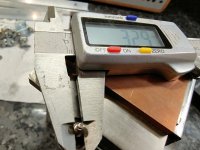
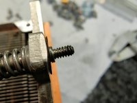
Guys would anyone have an inkling what the threads on these coolers might be? I'm not very good with imperial, which I am assuming they are seeing as they are on 3.5" centres. They are 3.3mm diameter to the thread outer, which I assume is 1/8" and have quite a fine pitch.
Attachments
- Home
- Amplifiers
- Solid State
- Alpha Nirvana 39w 8ohm Class A Amp