Both output and driver can be driven into saturation because the base can be driven above the collector. In a normal EF2 or CFP. with unity gain the VAS can’t generate more than the rail voltage. The CFP-with-gain can be fully driven with less than the power supply voltage. It is both its advantage and its weakness.
The driver collector is one Vbe drop below the rail, the current source cannot pull to the
negative rail due to the zener on the base and the VAS is current limited by the emitter
degeneration so I would not expect hard drive into saturation but I'll keep an eye out for it.
Dropping the front end supply voltage as was done in the Tiger .01 and Bryston solves this
issue and I'll keep it in mind as a solution.
Thanks for your comments, nice insight into the design.
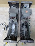
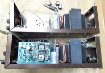
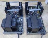
More madness. A friend is downsizing and he included these Tiger .01 s in a trade.
The board is much more complex due to the dual differential front end, output
protection, and Darlington output stage.
One looks, nearly complete but the keen eye might catch that C8 is lifted at one end.
The other is missing the board and heat sinks.
I'll probably use the empty chassis to test more complicated mods.
Attachments
Last edited:
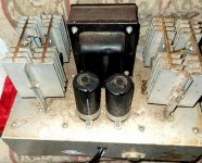
The mono UT shown above was a single MK II.
Here are a pair of mono UT s originals from ebay, claim was that they worked perfectly but I never
powered them up do to likely needing a recap. They are the original version but they do
have all 6 of the 100R upsized to 1W. SWTPC probably made this improvement when so
many had the resistors burning up. Output transistors have 036 and 044 markings on both
units, perhaps 36 and 44 th weeks of 1980 - anyone know?
They look completely original with no burn marks or signs of ever being repaired.
https://www.diyaudio.com/forums/attachment.php?attachmentid=795420&d=1573967420
Attachments
Last edited:
The mono UT shown above was a single MK II.
Here are a pair of mono UT s originals from ebay, claim was that they worked perfectly but I never
powered them up do to likely needing a recap. They are the original version but they do
have all 6 of the 100R upsized to 1W. SWTPC probably made this improvement when so
many had the resistors burning up. Output transistors have 036 and 044 markings on both
units, perhaps 36 and 44 th weeks of 1980 - anyone know?
They look completely original with no burn marks or signs of ever being repaired.
https://www.diyaudio.com/forums/att...573967420-tiger-amp-madness-swtpc-ut-pair-jpg
If those are anything like the original tiger, I simulate the lower 100R dissipation at potentially about 7.5W (15W *50%) for a +/-42V supply. Of course this is hard clipping but could happen easy. Note that 21V on 100R is 4.4W but that doesn't include the driver current. In any case, even 1W seems very optimistic.
In this position, wire wound resistors may be too inductive so finding a non inductive 10W resistor may be difficult.
The "upper" 100R resistors do not need to be as big and 1W may be enough.
Last edited:
They are the original (first version) Universal Tiger (UT) and yes they have +/- 42V
supply at idle. I simmed .9 W on R12,14 and the feedback resistors at full sine
power. Just did a hand calculation and got 1.9W full power sine so perhaps I'm
mis-remembering the simulation. Resistors have to be de-rated so I'd just use
5W resistors. And of course a full power square wave would heat them even more
than the 1.9W calculation. This is one reason that I plan to go to Darlington outputs
since then those resistor values go up by roughly 10X and power levels divided by 10.
One goal is to be able to use this amp on the bench with any waveform from a function
generator with any reasonable load on the output even open circuit. So, thinking it over
A full output square wave into no load should be allowed for and your calculations are
correct. The resistors should be 4W min, 5W to have some margin so that will be the new
recommendation. I knew that 1W was not enough but that is what SWTPC was using.
Thanks for pointing it out.
The pair that I posted in #43 have slight rust starting on the chassis which is bare steel,
any suggestions for cleaning them up without painting them?
Found this, the Showman chassis later in the thread cleaned up nicely after a soak in
Krud Kutter - never heard of it:
Restoring a corroded & rusty Fender chassis | Telecaster Guitar Forum
any suggestions for cleaning them up without painting them?
Found this, the Showman chassis later in the thread cleaned up nicely after a soak in
Krud Kutter - never heard of it:
Restoring a corroded & rusty Fender chassis | Telecaster Guitar Forum
Last edited:
Oxalic acid dissolves rust slightly. Found in Barkeeper's friend powder cleaner. Use slight water spray, fine steel wool to avoid scratches.
Prussic acid can convert trivalent FeO red flaky to bivalent FeO, black, sticky. Will turn the surface black or blue. I use an industrial chemical made fished out of factory dumpster, but the vendor is out of business. OsPho was a trade name 45 years ago. Gallon jug included the chemical, also detergent. Paint on, allow to sun dry. Rinse powder off with water, dry. Marine paint suppliers should have some.
I have heard gunsmiths have a source of the chemical for gun blueing.
Bumper restorers should be able to chrome cadmium or nickle plate it for you. Detail shops sometimes have a gold plate brush rig for door handles & hood ornaments.
Last edited:
I am not an engineer, just an old, long ago SWTPC user. I am a little surprised to read some of the comments about the Tigers blowing up, etc. Just today, I read the article in Pop Electronics I think, about the Universal Tiger, the 125 Watt max amp. There was a very extensive explanation about WHY the amp was so indestructible under any and all conditions. So that is why I find it odd now to see this seeming discrepancy. I don't think there were such things as subwoofers back then (1969+), but wouldn't it be great to get one of those UTs, or even the Tigersaurus (250 watt) in a true bi-amped sub-woofer service, with a 15 or 18" woofer (not just a speaker-level cross-over). Even my current little 12" with a simple automotive 60 watt amp is pretty good, paired with small ARs.
I am a little late to this party, however...
Back when I was in high school, and living in the Toronto area in the early 1970s, my best friend and fellow electronics geek ordered a PCB for a single channel "Universal Tiger" from SWTP which he built, but could never get working.
As soon as power was applied, the 40409 / 40410 driver stage went into thermal runaway and took out the transistors. I can't recall whether the output stage was connected and affected as well, or whether we were able to set up a test without the final stage.
Regardless, after replacing the fried transistors at least once, the project was abandoned as unworkable, however this was largely due to our lack of both test equipment and technical knowledge.
Fast forward to 2021 -- while browsing eBay, I came across a listing for a pair of these boards, the power supply components (less the transformers), and the miscellaneous chassis parts supposedly pulled from a working stereo unit, which I picked up with the intention building a pair of monoblocks just for the heck of it.
After reading this thread and other online information, I am aware of the limitations and shortcomings of the original design, however I feel that it would still be fun to complete this build, and declare victory over the initial failure to get the circuit working.
I was wondering if anyone still had any bare PCBs that incorporate any of the mods mentioned in this thread, or whether it would be worthwhile to use the information here to design new boards using KiCAD or a similar CAD program.
I am somewhat of a newbie with CAD in general, and see where building the component libraries using the original parts specified in Dan Meyer's original design would be (at least to me) a bit of a major undertaking.
Thanks,
Charles Kaross
K5QED
I found what might have been a plastic or universal Tiger in a surplus store about 20-25 years ago (slim brown case with brown canemetal cover, pair of meters on the front).. I gutted it to make a small subwoofer amp using a pair of OPA541s and an OPA4134 for the input filter section. If I remember correctly, the thing had TIP2955 and TIP3055 TO-247 outputs, so it was a lowish power Tiger.
Last edited:
I also am a fan of the universal tiger.
Nowadays almost all amplifiers have a longtailed pair input stage of 2 PNP transitors instead of NPN, I believe this is a better way of design.
I rebuild the input stage and I think it sounds better than the original one with the PNP transistors.
What do you think ?
PS
You have to change more in the circuit to make it work.
I had a Universal Tiger for about 6 years. It did not blow up. I got rid of it when I moved.
http://www.wass.net/othermanuals/SWTPC.pdf
http://www.wass.net/othermanuals/SWTPC.pdf
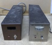
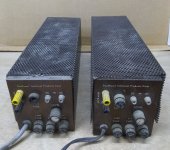
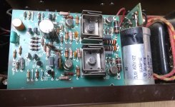
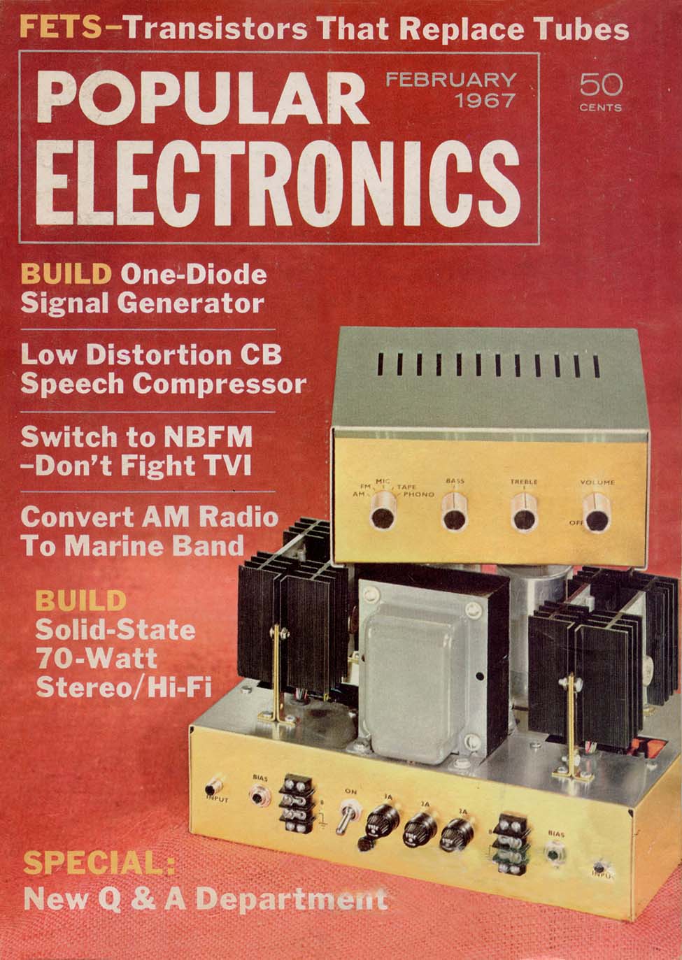
Good day all, I have an amp here that I have been told is a "Tiger" amplifier but I cannot find a visual match for it.
Could anyone please let me know what I have, is it worth recapping and what parts would you use?
Also absolutely any info, brochures, schematics would all be extremely helpful and appreciated!
Cheers!


Could anyone please let me know what I have, is it worth recapping and what parts would you use?
Also absolutely any info, brochures, schematics would all be extremely helpful and appreciated!
Cheers!
Attachments
It might be its cousin, the Brute 70
Of course, worth recapping and updating; you have the most expensive parts:chassis - PT - Heatsinks ... anything else can be upgfraded/replaced fo burger money.
https://deramp.com/swtpc.com/PopularElectronics/Feb1967/PE_Feb1967.htm
Of course, worth recapping and updating; you have the most expensive parts:chassis - PT - Heatsinks ... anything else can be upgfraded/replaced fo burger money.
https://deramp.com/swtpc.com/PopularElectronics/Feb1967/PE_Feb1967.htm

- Home
- Amplifiers
- Solid State
- Tiger Amp Madness!