Hello All,
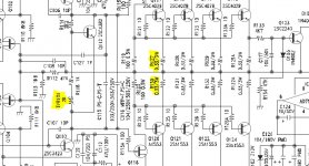
I just acquired a Parasound HCA-1500A with an almost dead left channel, as volume was barely perceptible. After taking things apart, I found 2 issues: two blown fuses on the main board, and a cold solder joint on the stereo-bridge switch. The left channel came to life, but runs warmer than the right channel. I'm attempting to adjust the bias, and need your help to identify the emitter transistors correctly. On the schematic, I highlighted the trim pot TVR101, so am I correct to assume that a measurement should be taken across R130 and R127? Parasound's recommendation for the bias voltage for this amp is 15 mV, +/-2 mV. I built Rod Elliott's P101 so I am somewhat familiar with bias setting (not a pro by any means).
Thanks in advance for your guidance.
Hong
Attachments
Thanks @rayma.I was able to set the bias on the left channel - the one that didn't originally work - to 15 mV.
However, the right channel shows 0 mV, and turning the trim pot either direction didn't do squat. Checked the emitter resistors on that channel and values are normal (0.33R). I guess I need to replace the 2K trim pot. Does anyone know which brand or model it is? Thanks.
However, the right channel shows 0 mV, and turning the trim pot either direction didn't do squat. Checked the emitter resistors on that channel and values are normal (0.33R). I guess I need to replace the 2K trim pot. Does anyone know which brand or model it is? Thanks.
Attachments
That may not be the problem, but you can replace it anyway.
The channel works fine but I haven't put it through extensive testing, so it may exhibit more issues later. What are your thoughts? Thanks.
The channel works fine but I haven't put it through extensive testing, so it may exhibit more issues later. What are your thoughts? Thanks.
I would compare DC voltage readings between the good and bad channels, and post the results here.
I ordered new trimmer pots and will report back.
And your conclusion the pot needs replacement is based on?
You should check it with a meter and if ok solder it back on and make sure turning it does produce a change in collector-emitter voltage.
And your conclusion the pot needs replacement is based on?
You should check it with a meter and if ok solder it back on and make sure turning it does produce a change in collector-emitter voltage.
I hate it when you guys are right. Both trim pots are fine and vary from 15 ohms to 1.9K ohms. I think pulling the main board out and check for solder joints is my next step.
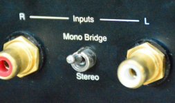
One poster PM'ed me about the same issue he had with the stereo-bridge switch on his Parasound amp, but I can say that after I corrected the cold solder joint, continuity checks are fine between the poles when switched up or down.
Thank you all.
Attachments
.........perhaps you can test continuity between the pot and 2sc4382 / Q112 with the ohmmeter
Yes, there is continuity between the trim pot TVR101 and the emitter leg of Q112. Same with the other channel between TVR201 and Q212. Thanks for the suggestion.
try to measure Q112/212 with a ohmmeter or the diode test , perhaps there is a "short" in the transistor........
No short to report @mjf. I'll work on it more this weekend. Work sucks. Thanks so much for your help.
OK, good news so far. I took the main board off the amp, went over all solder joints with a fine tooth comb, and re-soldered suspected joints. The previous owner also had the wrong fuse values, so I replaced them with slow blow fuses and the correct amperage. Both channels are biasing fine, the heat sinks are around 40 degrees C and 42C. I'm letting the amp run for the next hour to allow it to stabilize. I think it boils down to a bad stereo-mono bridge switch, and wrong fuses. Thanks all.
Hong
Hong
Last edited:
- Status
- This old topic is closed. If you want to reopen this topic, contact a moderator using the "Report Post" button.
- Home
- Amplifiers
- Solid State
- Emitter Resistors Location - Parasound HCA-1500A