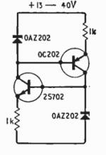
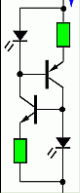
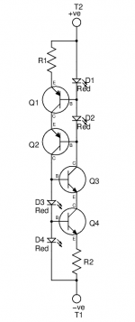
This current source was first described by Peter Williams in the July 1967 issue of Wireless World and is shown in the first schematic. The most commonly used variant replaces the zener diodes with leds as shown in the second schematic. Williams himself noted that it is theoretically possible that the circuit may not self start, indeed I suspect that most simulations will not self start without a "kicker" resistor. However, in real life, the circuit reliably self starts regardless of ( within sensible limits ) voltage, current, temperature, transistor matching, deliberate transistor mismatching, and the presence or absence of light. I have verified that the circuit self starts at -20C, so if the circuit is kicked into life by leakage current through the transistors it must be very small. In addition to the tests I have used this circuit as a two terminal current source in a myriad of amplifier projects over the last 20 years with no problem.
My questions then are:- (1) Has anyone observed this circuit, or a variant of it, failing to start and (2) Has anyone got a convincing explanation, other than miniscule leakage currents, as to why the Williams ring of two current source always starts so reliably.
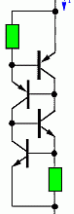
Finally, in the third schematic the leds have been replaced with transistors and this circuit too, self starts reliably. I find that two terminal current sources make pcb layout easier and this variant has very good PSRR, potentially very low noise, and fairly low temperature sensitivity. I'll switch to using this variant rather than the led version.
Any comments, particularly as regards shortcomings of this circuit are welcome.
My questions then are:- (1) Has anyone observed this circuit, or a variant of it, failing to start and (2) Has anyone got a convincing explanation, other than miniscule leakage currents, as to why the Williams ring of two current source always starts so reliably.
Finally, in the third schematic the leds have been replaced with transistors and this circuit too, self starts reliably. I find that two terminal current sources make pcb layout easier and this variant has very good PSRR, potentially very low noise, and fairly low temperature sensitivity. I'll switch to using this variant rather than the led version.
Any comments, particularly as regards shortcomings of this circuit are welcome.
Attachments
I don't think I have ever observed this exact circuit failing to start (but I am not completely certain: I know that some schemes relying on positive feedback sometimes failed to start naturally, but I do not remember which ones).
Anyway, I generally prefer to be safe, and I always include a starter to ensure peace of mind.
The sim always starts without any problem (but this is not a proof for anything)
This could also interest you:
Improved 2W current sources (II)
Anyway, I generally prefer to be safe, and I always include a starter to ensure peace of mind.
The sim always starts without any problem (but this is not a proof for anything)
This could also interest you:
Improved 2W current sources (II)
2 terminal current sources
Chalky,
To ensure that the `Ring of 2' starts, you can put a 1megohm resistor between the two bases. This `leakage' current will ensure it starts.
Are you aware of the NSIC2020jbt3, NSIC2030jbt3 and NSIC2050jbt3 current sources? These are 20mA, 30mA and 50mA `ring of two' current sources - SMB package, 120v and cheap. Digikey has thousands of them. I frequently use the NSIC2020's.
For less that 20mA, I normally use a DN2530 (sot89) depletion mode mosfet, plus two resistors. Use about 500ohms for the gate resistor, and the other resistor sets the current. There is also a DN2540 in a To220 for higher currents and voltage. Unlike jfets, the DN2530's have a reasonably consistent Vgs threshold (~ 2.2volts). For better performance you can cascode one with a second DN2530.
Regards,
Paul Bysouth
The self-starting depends on the comparative sizes of the transistor leakage to zener/LED leakage - if the zener/LED leakage is greater it will not fire up. Fortunately the transistor leakage is amplified by its current gain so its highly likely to be the larger.
This argument doesn't apply to variant 3 I think...
I wonder if employing the extra transistor for cascoding is a better use of it, performance-wise? And it allows more freedom in choosing best transistor for each role.
This argument doesn't apply to variant 3 I think...
I wonder if employing the extra transistor for cascoding is a better use of it, performance-wise? And it allows more freedom in choosing best transistor for each role.
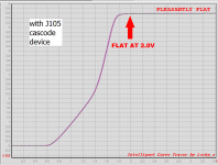
LM334 + J105 cascode requires 5 parts total and always starts up
LM334 makes quite a nice 5.5 mA current source, works down to 2.0-2.2 volts
_
- Two 3-legged TO-92s
- Two resistors
- One silicon diode
LM334 makes quite a nice 5.5 mA current source, works down to 2.0-2.2 volts
_
Attachments
Thanks for all the feedback and info guys, lots to think about here. I don't really think that startup resistors are necessary with the Williams current source but the emitter to emitter resistors suggested by John Rudge as an improvement ( in a subsequent Letter to the Editor of Wireless World ) and implemented by Elvee look to be a worthwhile addition. How did you calculate the value of these resistors Elvee? At the moment I'm trying to find the best solution for a 10mA 200V constant current source as part of a new solid state amplifier design, and the DN2540 suggested by Paul Bysouth looks a good possibility, as well as a higher power version of the Williams current source.
At the moment I'm trying to find the best solution for a 10mA 200V constant current source as part of a new solid state amplifier design, and the DN2540 suggested by Paul Bysouth looks a good possibility, as well as a higher power version of the Williams current source.
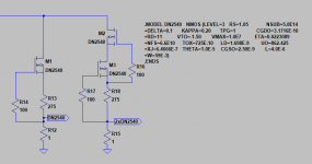
Two are better than one! R13 and R18 are the "set" resistors -- DMOS can vary quite a bit so they will have to be adjusted to fit -- this one is set for 5mA. ymmv
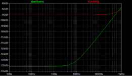
Once the PSRR gets better than +120dB stray capacitance, dust, grease etc. can affect measurements.
Attachments
If you plot the current-vs-voltage behavior of the post #11 circuit, where is the voltage "knee" at which current becomes an acceptably good apptoximation of constant?
My wild guess is ~(4 * Vfwd_led) which is around 6 volts, but would love to know the accurate number from the actual designer of the circuit.
My wild guess is ~(4 * Vfwd_led) which is around 6 volts, but would love to know the accurate number from the actual designer of the circuit.
I love this kind of current source:
Instead of an LED to offset the cascode transistor, I prefer a resistor because the low output resistance of the LED can make the cascode oscillate whereas the resistor has a dampening effect. This means that when changing output current, you need to adjust four resistors insetad of two.
A base resistor for stabilizing the cascode transistor did not work well for me in simulation for some unknown reason.
I have one question though:
I guess most people would make both halves equal, i.e. the current setting resistor the same and so do I.
However, I can't find suitable resistor values to get the exact output current I want.
How about making resistors slightly unequal for fine tuning?
I guess this should be okay. What do you think?
- It has incredibly high PSRR
- The cascoded variant has very high output impedance
- Since this is actually two CCS in parallel, noise is rather low
- Above the (rather high) compliance voltage, the output current is totally independent of the voltage across the CCS, especially with the cascoded variant
- With using a LED as reference, temperature stability is okay
Instead of an LED to offset the cascode transistor, I prefer a resistor because the low output resistance of the LED can make the cascode oscillate whereas the resistor has a dampening effect. This means that when changing output current, you need to adjust four resistors insetad of two.
A base resistor for stabilizing the cascode transistor did not work well for me in simulation for some unknown reason.
I have one question though:
I guess most people would make both halves equal, i.e. the current setting resistor the same and so do I.
However, I can't find suitable resistor values to get the exact output current I want.
How about making resistors slightly unequal for fine tuning?
I guess this should be okay. What do you think?
- Home
- Amplifiers
- Solid State
- Williams Ring of Two Current Source