The SLAM! AMTs I built have a high efficiency (100 dB/ 1 W / 1 meter), so I don't need that many Watts to drive them.
I'll be quite satisfied with 4 Watts, the AMT's resistance is 6 ohms, so 4.95 Vrms is sufficient.
The AMTs also have an outstanding resolution, but they are at the same time merciless in revealing any amplifier's misconduct.
My current 25 W class A amplifier is no exception.
I've been suggested to give up on complex amplifiers and instead try something simpler and with no feedback at all.
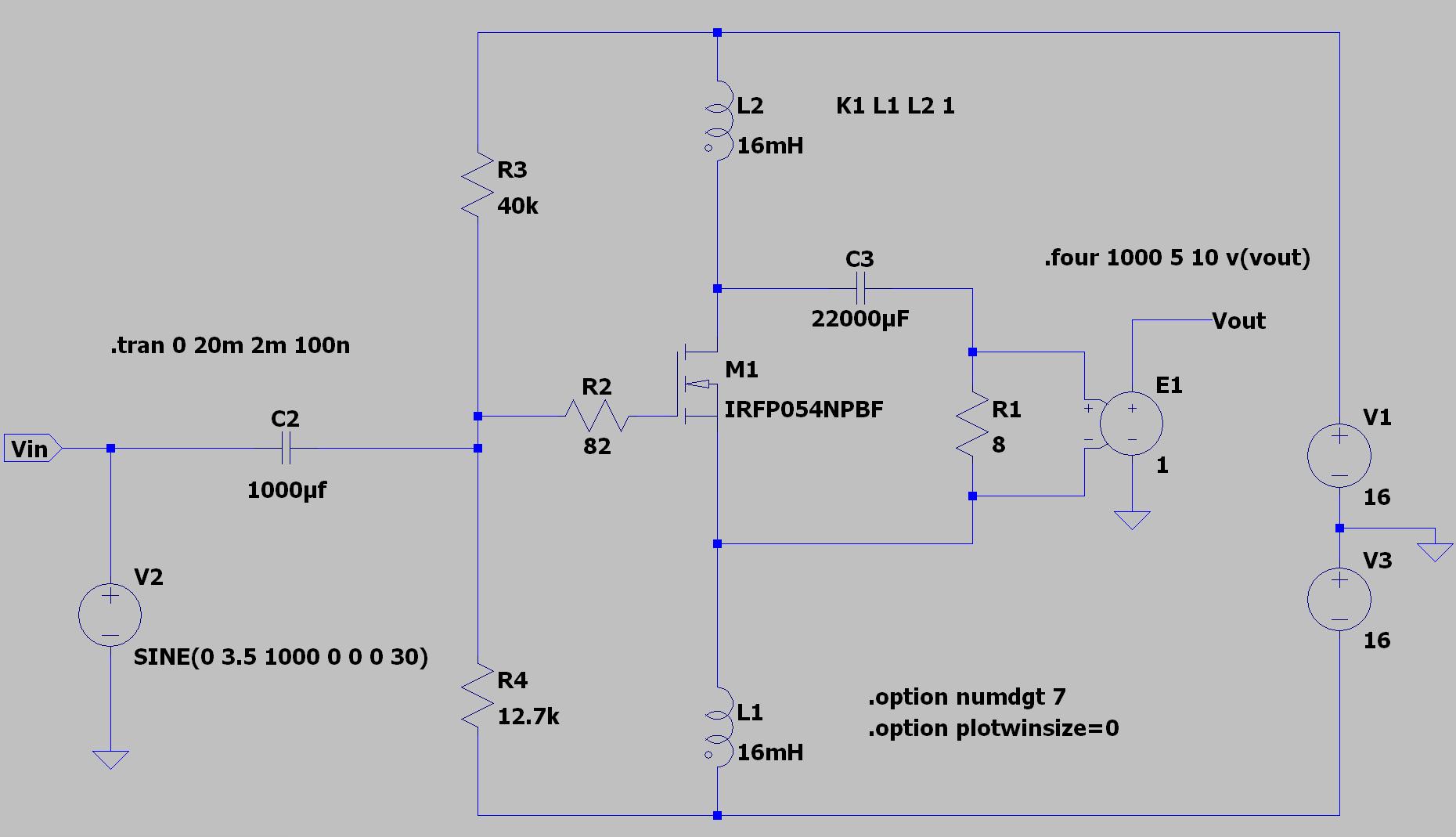
This is the SLAPS (Split load phasesplitter amplifier) amplifier I've been suggested by Circlomanen:
It amplifies only 2 times, so I need a pre-amplifier with 12 times amplification.
More to come...
I'll be quite satisfied with 4 Watts, the AMT's resistance is 6 ohms, so 4.95 Vrms is sufficient.
The AMTs also have an outstanding resolution, but they are at the same time merciless in revealing any amplifier's misconduct.
My current 25 W class A amplifier is no exception.
I've been suggested to give up on complex amplifiers and instead try something simpler and with no feedback at all.
This is the SLAPS (Split load phasesplitter amplifier) amplifier I've been suggested by Circlomanen:
An externally hosted image should be here but it was not working when we last tested it.
It amplifies only 2 times, so I need a pre-amplifier with 12 times amplification.
More to come...
Last edited:
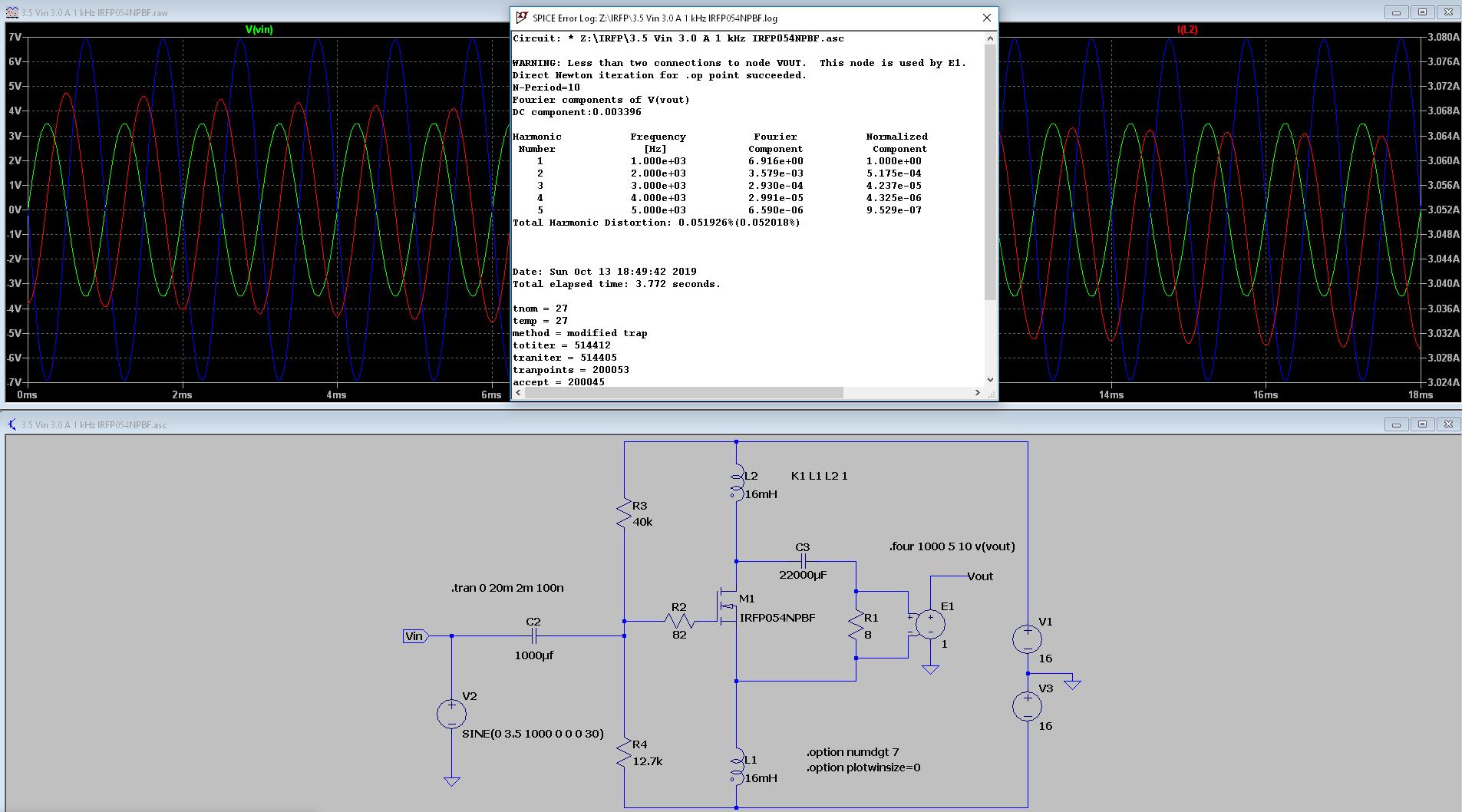
So what about reality?
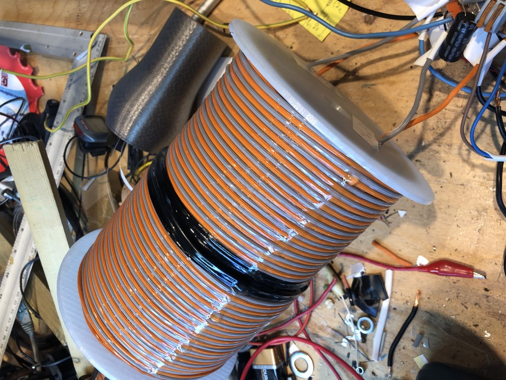
Coils:
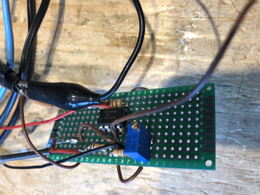
Preamp:
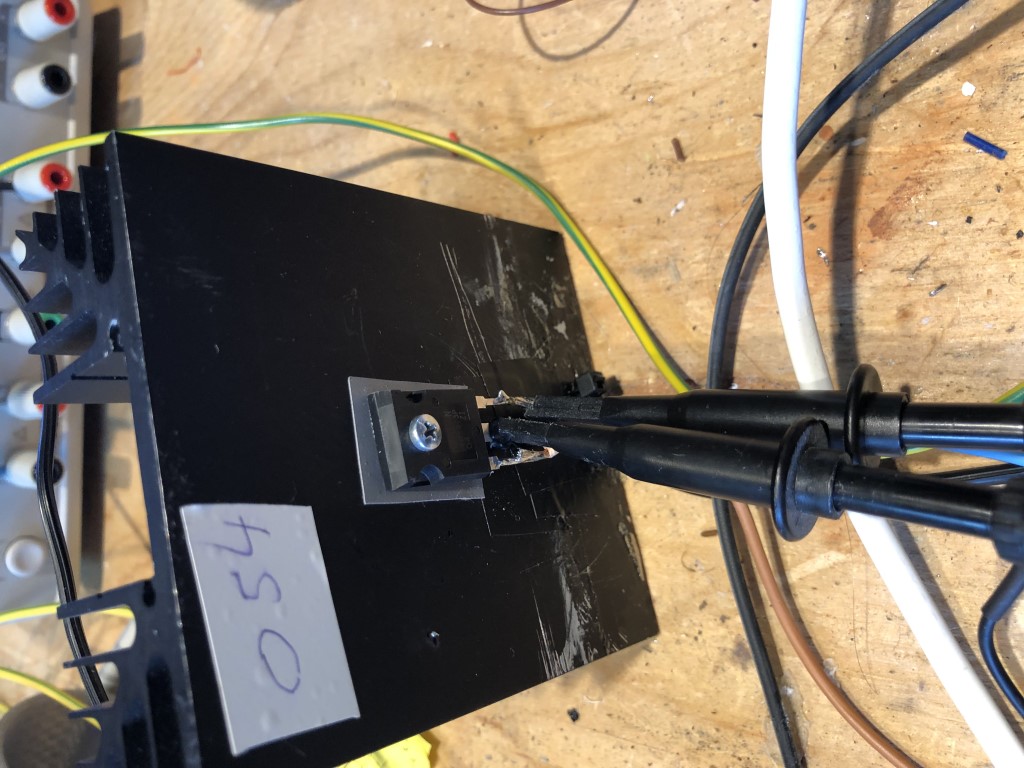
MOSFET:
Power supply:
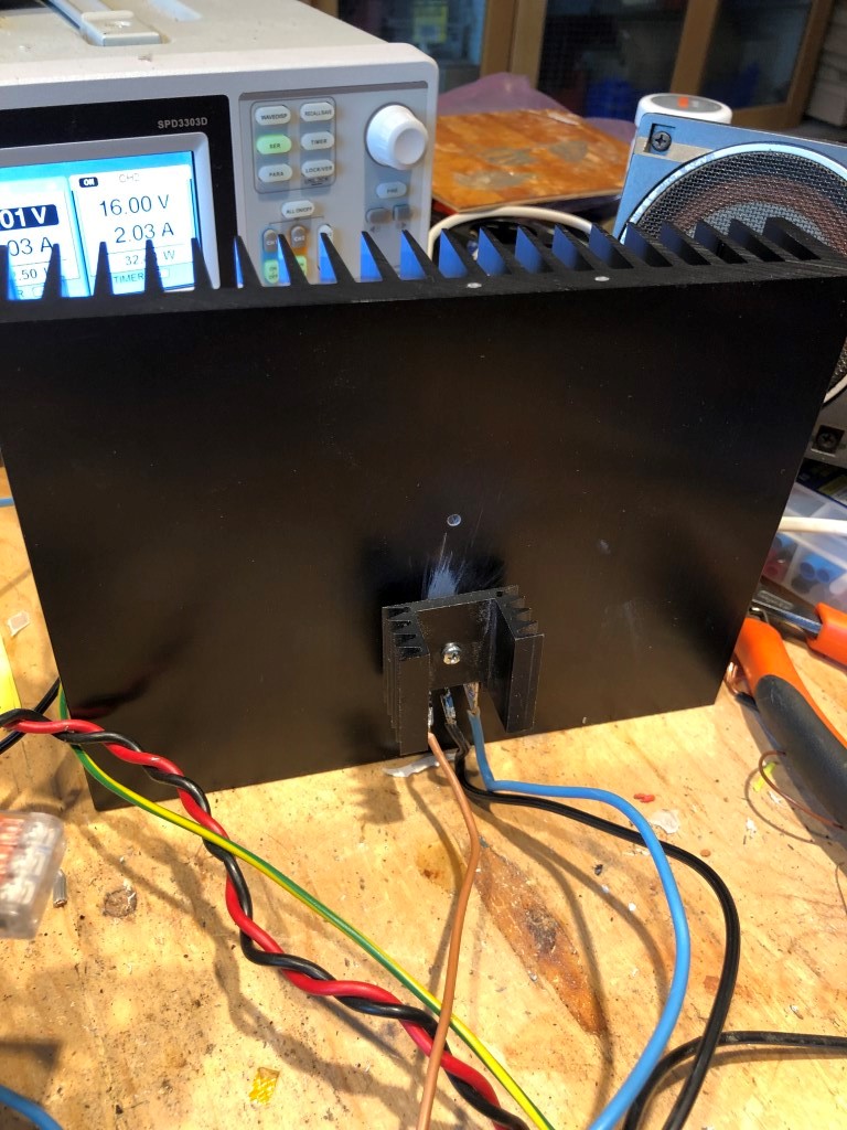
I found that the MOSFET got really hot, so I got a bigger heatsink and also put a smaller one on the top of the MOSFET.
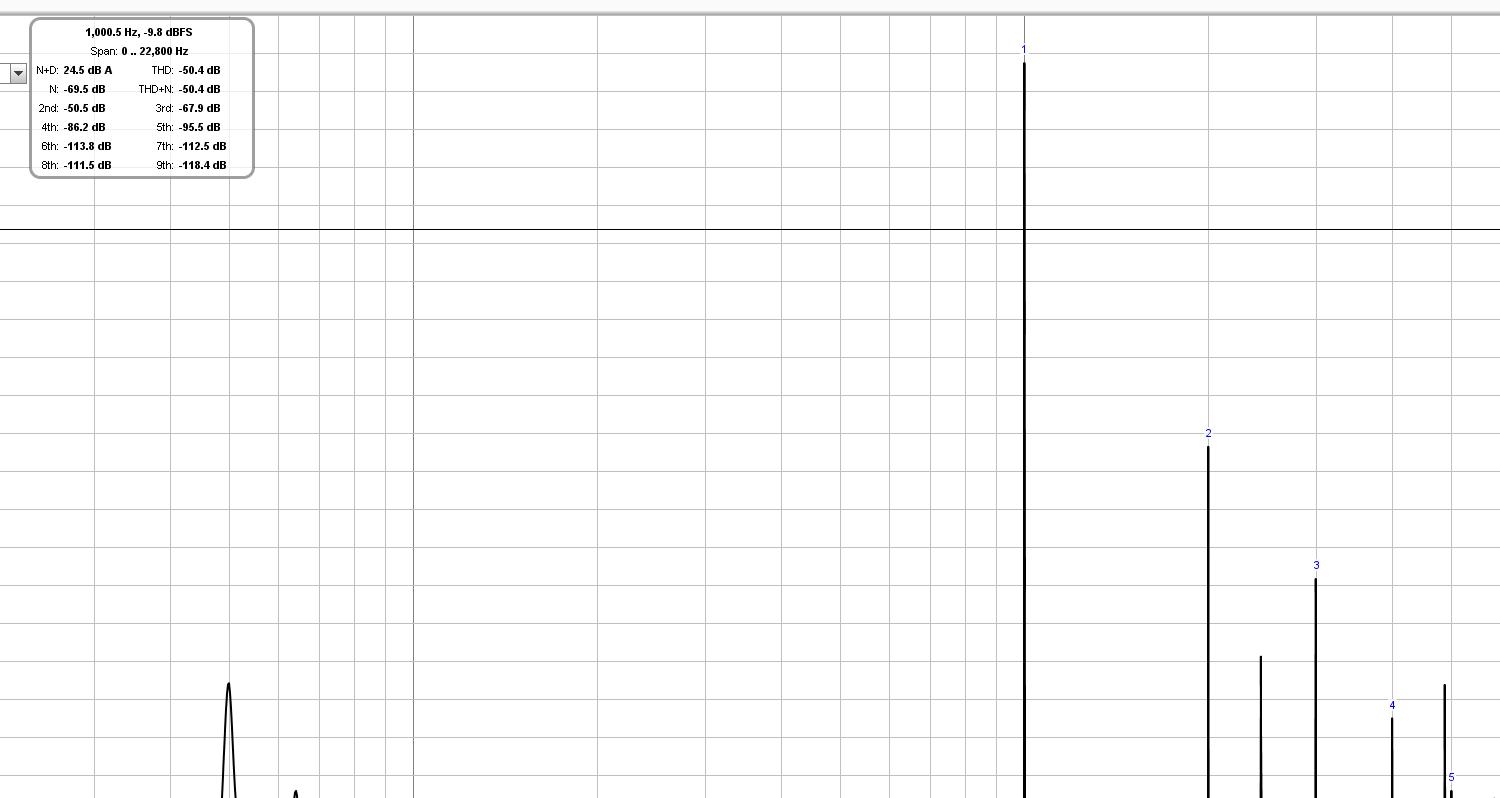
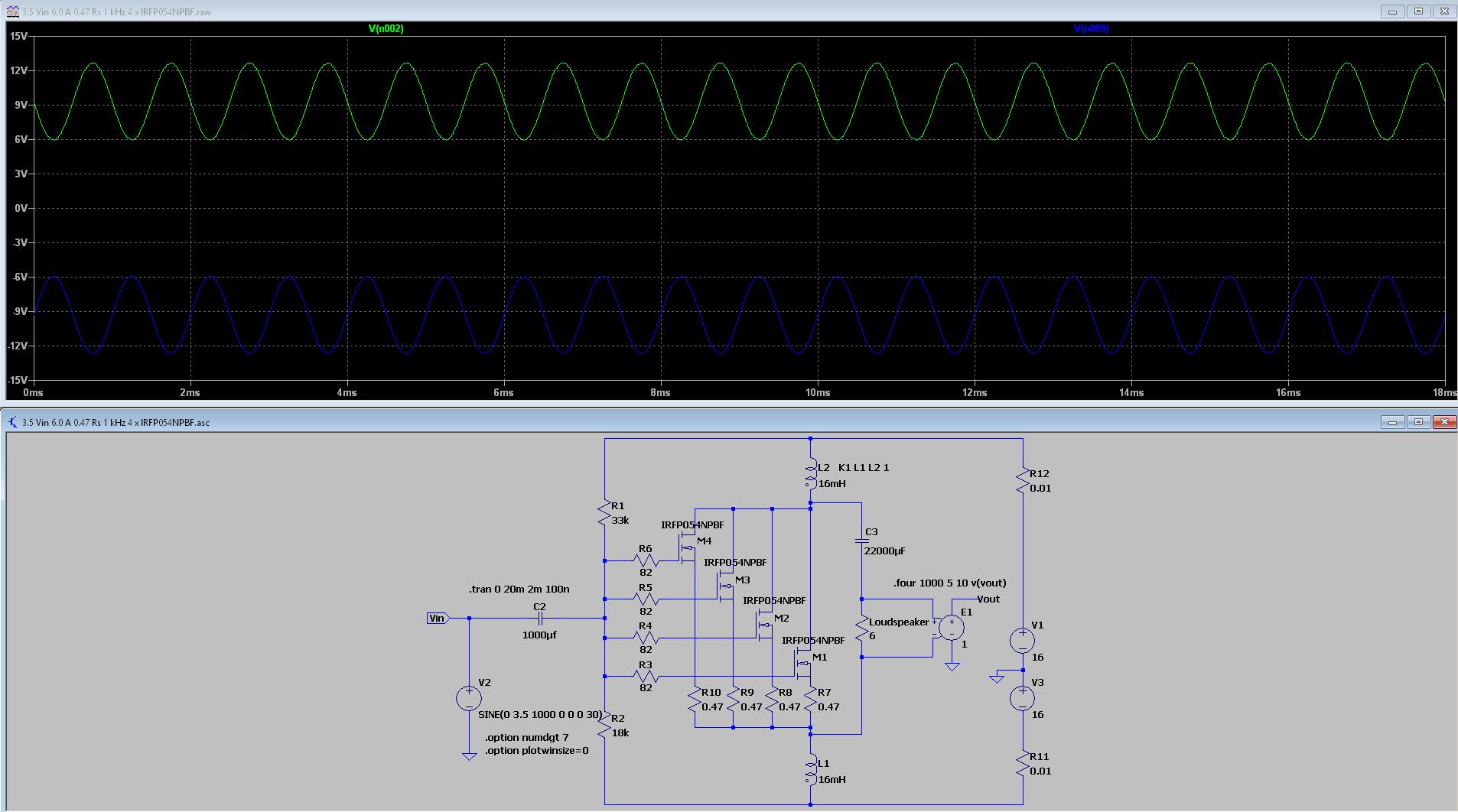
I connected a 8 ohm dummy load and let REW measure it using my EMU0402:
Not that nice as the LTSpice simulation, but the 2nd and 3rd relationship seems to be correct.
Now the wires is not ideal and I don't what the power supply contributes, but I'd say it is looking good so far.
Coils:
An externally hosted image should be here but it was not working when we last tested it.
Preamp:
An externally hosted image should be here but it was not working when we last tested it.
MOSFET:
An externally hosted image should be here but it was not working when we last tested it.
Power supply:
An externally hosted image should be here but it was not working when we last tested it.
I found that the MOSFET got really hot, so I got a bigger heatsink and also put a smaller one on the top of the MOSFET.
An externally hosted image should be here but it was not working when we last tested it.
I connected a 8 ohm dummy load and let REW measure it using my EMU0402:
An externally hosted image should be here but it was not working when we last tested it.
Not that nice as the LTSpice simulation, but the 2nd and 3rd relationship seems to be correct.
Now the wires is not ideal and I don't what the power supply contributes, but I'd say it is looking good so far.
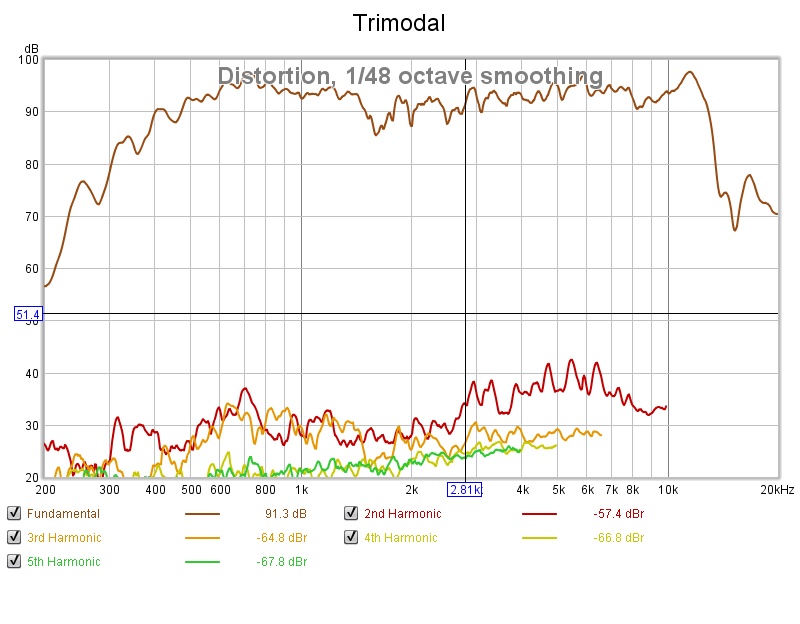
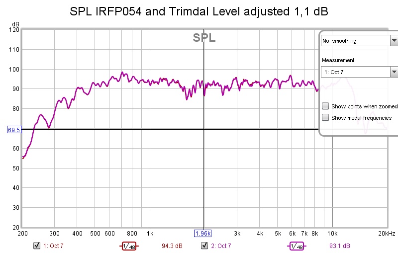
Time to measure with the AMT using REW and UMIK-1.
This is the middle range AMT, so it rolls off at 13 kHz.
SPL with a 1.1 dB matching:
No difference to mention.
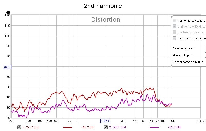
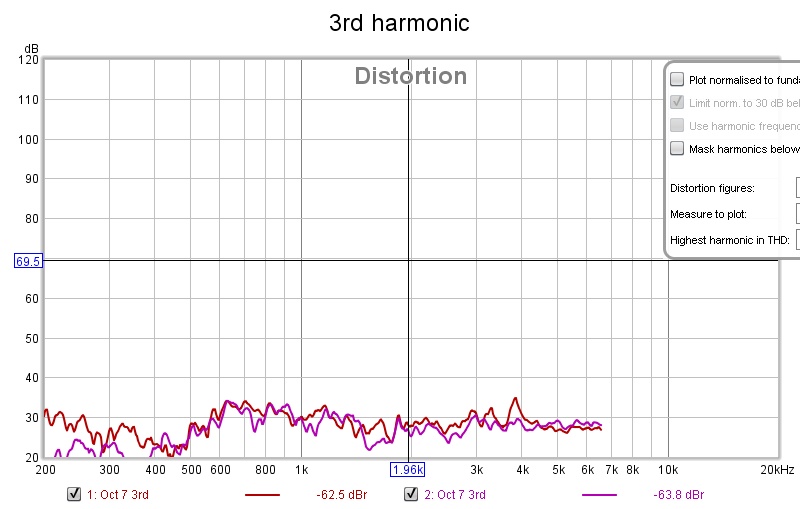
Distortion with the complex amplifier:
Distortion IRFP054:
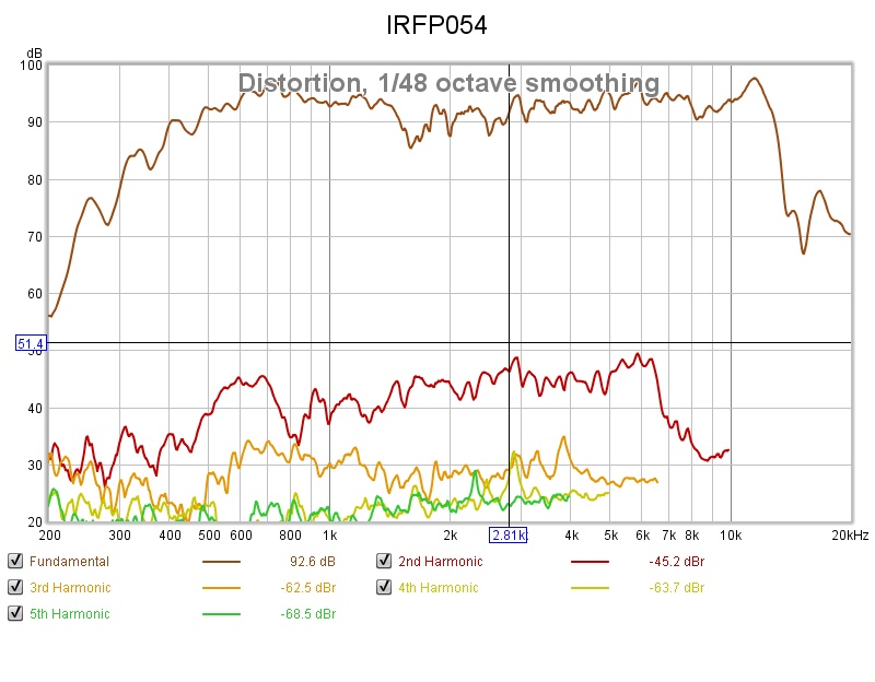
Both, 2nd:
Both 3rd::
Here I am a little bit surprised that the two amplifiers behave almost the same.
But it could the AMT distortion that takes over.
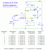
Both THD up to 9th:
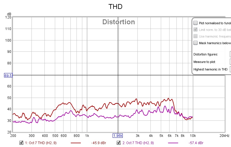
2nd order is the dominant part as we have seen earlier.
I'd say that the simple amplifier looks promising considering the state of the circuitry.
I need four amplifiers as there's a treble AMT as well and they are all driven active.
But before I start to build proper circuitry and proper power supply and casing and so on, I think that there are room for improvements.
An Id of 3A makes the MOSFET really hot, I guess it will not last long.
The bigger heatsink is at 72 degrees Celsius and the smaller on top of the MOSFET is at 84 degrees Celsius.
For sure, the MOSFET's leads can be soldered to a bigger copper area, but it is still to hot.
And what about those 2nd distortion levels?
This is the middle range AMT, so it rolls off at 13 kHz.
SPL with a 1.1 dB matching:
An externally hosted image should be here but it was not working when we last tested it.
No difference to mention.
Distortion with the complex amplifier:
Distortion IRFP054:
Both, 2nd:
An externally hosted image should be here but it was not working when we last tested it.
Both 3rd::
An externally hosted image should be here but it was not working when we last tested it.
Here I am a little bit surprised that the two amplifiers behave almost the same.
But it could the AMT distortion that takes over.
Both THD up to 9th:
2nd order is the dominant part as we have seen earlier.
I'd say that the simple amplifier looks promising considering the state of the circuitry.
I need four amplifiers as there's a treble AMT as well and they are all driven active.
But before I start to build proper circuitry and proper power supply and casing and so on, I think that there are room for improvements.
An Id of 3A makes the MOSFET really hot, I guess it will not last long.
The bigger heatsink is at 72 degrees Celsius and the smaller on top of the MOSFET is at 84 degrees Celsius.
For sure, the MOSFET's leads can be soldered to a bigger copper area, but it is still to hot.
And what about those 2nd distortion levels?
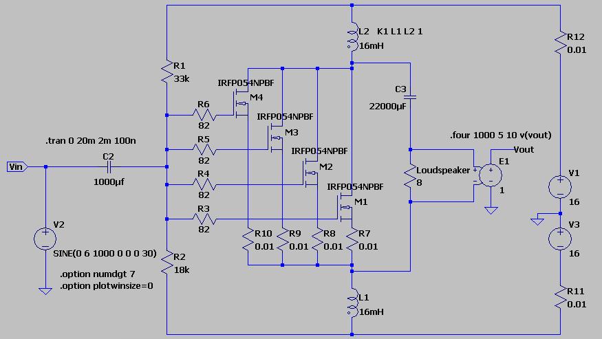
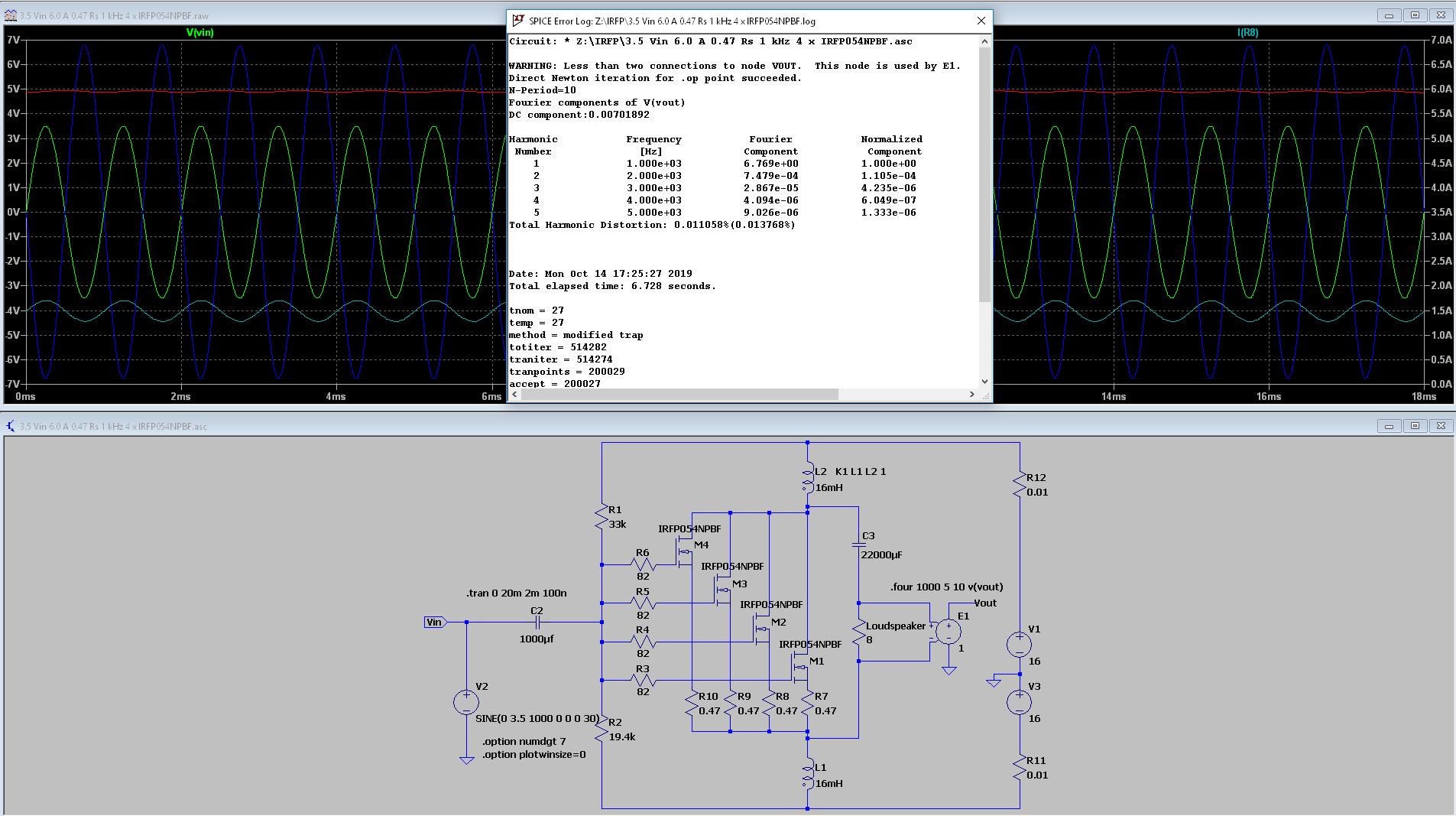
Four is better than one
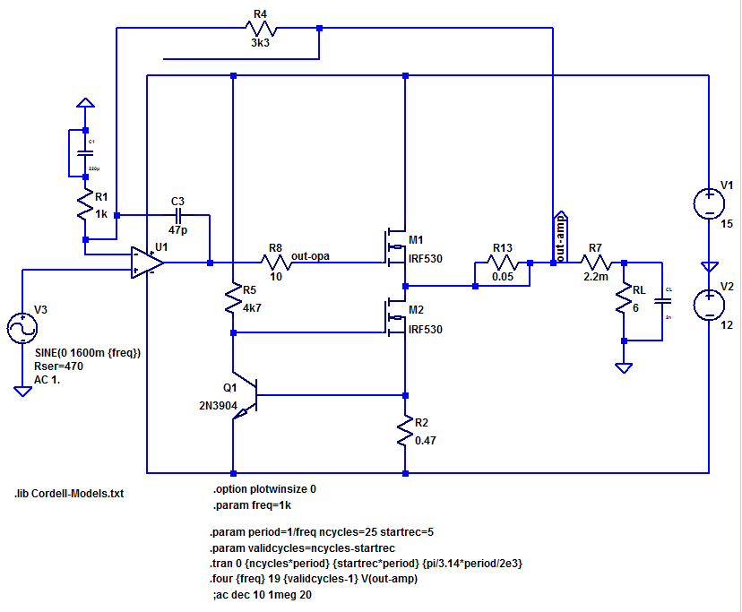
So I thought of have four MOSFETs in parallel:
The resistor R8 and up is used to be able to measure current.
I changed the bias to give 1.5 A through each MOSFET; I think that should give a more normal temperature.
So the current through the coils is 6A.
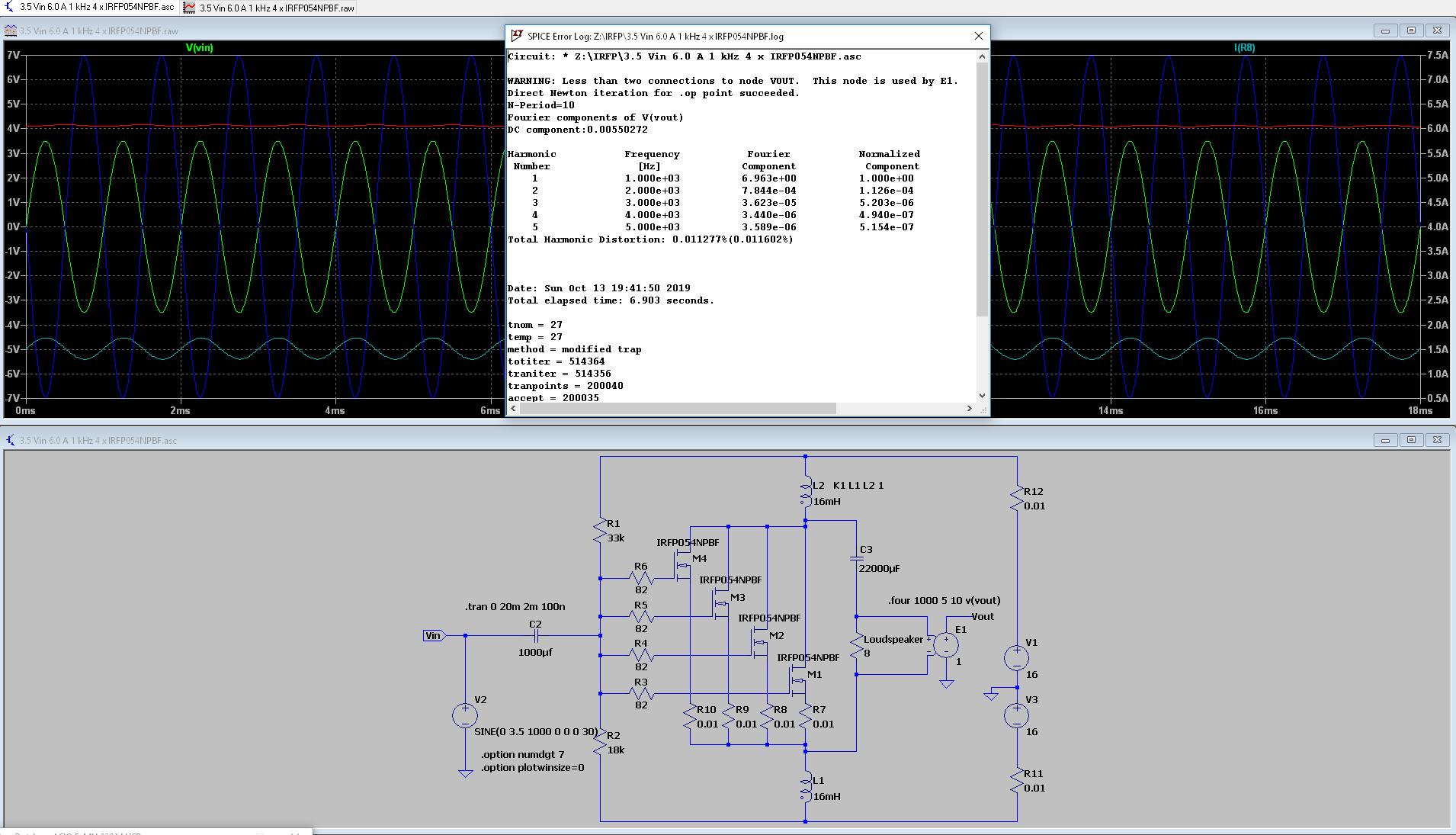
LTSpice have no trouble with this:
The distortion is down to THD -79 dB (3rd at -105,7 dB!) and I reckon that noise levels are down as well.
So now comes my question:
But how come the bias now is higher than with the single MOSFET one above?
It corresponds for sure with the Id of 6A for one MOSFET, but there are now four.
Is the LTSpice simulation correct?
So I thought of have four MOSFETs in parallel:
An externally hosted image should be here but it was not working when we last tested it.
The resistor R8 and up is used to be able to measure current.
I changed the bias to give 1.5 A through each MOSFET; I think that should give a more normal temperature.
So the current through the coils is 6A.
LTSpice have no trouble with this:
An externally hosted image should be here but it was not working when we last tested it.
The distortion is down to THD -79 dB (3rd at -105,7 dB!) and I reckon that noise levels are down as well.
So now comes my question:
But how come the bias now is higher than with the single MOSFET one above?
It corresponds for sure with the Id of 6A for one MOSFET, but there are now four.
Is the LTSpice simulation correct?
Remember what Einstein said about "as simple as possible, but no simpler"? Well, this circuit qualifies as "too simple" in my book. You've got a triangle of complexity - performance - power consumption going on, and in this case this means that by the time you get acceptable performance out of it, it'll be a real power hog. The only thing you've gained from this is an amplifier limiting the driver's distortion rather than vice versa. It is rather clever in that the coupled inductors cancel out magnetic flux from DC current (perfectly in theory, more or less imperfectly in practice).
LTspice inductor models do not model ferrite-related nonlinearity by default, and I'm not sure how far I'd trust MOSFET models for accurate modelling of distortion.
Also, there is no such thing as 4 exactly identical transistors in real life - current sharing resistors are probably a must.
If you insist on something simple with inductive load, here's what I would do:

(supply rail bypassing not included)
This, however, would require a rather substantial gapped choke. If the inductor doesn't work out, a transistor CCS may be more attractive:
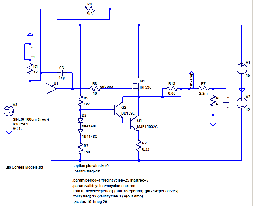
Or perhaps more elegant:
While you're obviously free to increase gain if needed, I've left it at 4.3 now, since I can't imagine why you would need a gain of 24 (28 dB) in the power amp for a 100 dB/W/m driver. I mean, you'd probably be coming out of the crossover at up to 1 Vrms (give or take), with a noise floor that may not be too much below -104 dBV (-110 dB re: 2 Vrms), depending on your DAC. You might need 16 dB, but but probably not any more.
I picked an IRF530 because good MOSFETs for linear applications tend not to be low rDSon types, quite the contrary.
The 3rd circuit still isn't ideal in that current draw alternates between the positive rail and the load, while negative rail current is constant... you'd have to make this a single-supply circuit with all-negative supply, but then you've just swapped signal currents going through a power filter capacitor for signal currents going through an output coupling capacitor... happier power supply, less happy load, not to mention the whole dealing with power-on/off transients business.
LTspice inductor models do not model ferrite-related nonlinearity by default, and I'm not sure how far I'd trust MOSFET models for accurate modelling of distortion.
Also, there is no such thing as 4 exactly identical transistors in real life - current sharing resistors are probably a must.
If you insist on something simple with inductive load, here's what I would do:
(supply rail bypassing not included)
This, however, would require a rather substantial gapped choke. If the inductor doesn't work out, a transistor CCS may be more attractive:
Or perhaps more elegant:
While you're obviously free to increase gain if needed, I've left it at 4.3 now, since I can't imagine why you would need a gain of 24 (28 dB) in the power amp for a 100 dB/W/m driver. I mean, you'd probably be coming out of the crossover at up to 1 Vrms (give or take), with a noise floor that may not be too much below -104 dBV (-110 dB re: 2 Vrms), depending on your DAC. You might need 16 dB, but but probably not any more.
I picked an IRF530 because good MOSFETs for linear applications tend not to be low rDSon types, quite the contrary.
The 3rd circuit still isn't ideal in that current draw alternates between the positive rail and the load, while negative rail current is constant... you'd have to make this a single-supply circuit with all-negative supply, but then you've just swapped signal currents going through a power filter capacitor for signal currents going through an output coupling capacitor... happier power supply, less happy load, not to mention the whole dealing with power-on/off transients business.
Attachments

Here I am a little bit surprised that the two amplifiers behave almost the same.
But it could the AMT distortion that takes over.
Yes. The AMT own distortion will dominate over the amplifiers level of distortion.
You should make a distortion-measurement comparing the total level of second harmonic with the AMT coupled with the leads reversed to the amp.
"Triodity" to cancel loudspeaker distortion
See this thread in the Pass section of this forum.
I would not worry about that low level of second harmonic. I am more worried about transient and dynamic stability while driving a reactive load like a loudspeaker. A steady state or swept sine wave measurement does not say that much about the sound quality of an amp.
I prefer the much more stable and direct feed forward error correction in the amp you are building above using a global negative feedback for low distortion and low output impedance.
The feed forward error correction is stable and useful up to 1,5 MHz and does not need any filtering to avoid HF-instability while driving a reactive load through long cables.
The simplicity of the amp coupled with the use of feed forward error correction does give a very stable and nice behaving amp while driving highly reactive loads with non-linear signals.
4 parallel devices without any substantial current sharing resistors will have 4 times the transconductans of a single device.
If you want to use parallel devices you will need to match them closely and use current sharing resistors of a higher value then you have in your simulation. 0,22 - 0,5 ohm or so.
But I would prefer a lower voltage from the power supply to keep the single device cooler and I would not be worried about some small amounts of second harmonics.
The feed forward error correction is stable and useful up to 1,5 MHz and does not need any filtering to avoid HF-instability while driving a reactive load through long cables.
The simplicity of the amp coupled with the use of feed forward error correction does give a very stable and nice behaving amp while driving highly reactive loads with non-linear signals.
But how come the bias now is higher than with the single MOSFET one above?
4 parallel devices without any substantial current sharing resistors will have 4 times the transconductans of a single device.
If you want to use parallel devices you will need to match them closely and use current sharing resistors of a higher value then you have in your simulation. 0,22 - 0,5 ohm or so.
But I would prefer a lower voltage from the power supply to keep the single device cooler and I would not be worried about some small amounts of second harmonics.
Thanks sgrossklass for your answer, but the simple circuit is what I'll go for.
See Circlomanen's answer.
It'll be an easy thing to adjust if I find noise levels too high.
I have no trouble with the noise levels with my current amplifiers.
See Circlomanen's answer.
Remember what Einstein said about "as simple as possible, but no simpler"? Well, this circuit qualifies as "too simple" in my book. You've got a triangle of complexity - performance - power consumption going on, and in this case this means that by the time you get acceptable performance out of it, it'll be a real power hog. The only thing you've gained from this is an amplifier limiting the driver's distortion rather than vice versa. It is rather clever in that the coupled inductors cancel out magnetic flux from DC current (perfectly in theory, more or less imperfectly in practice).
See Circlomanen's answer.
Good, I've added 0.47 ohm resistors.LTspice inductor models do not model ferrite-related nonlinearity by default, and I'm not sure how far I'd trust MOSFET models for accurate modelling of distortion.
Also, there is no such thing as 4 exactly identical transistors in real life - current sharing resistors are probably a must.
Well, +28 dB is what my current amplifiers have in gain.While you're obviously free to increase gain if needed, I've left it at 4.3 now, since I can't imagine why you would need a gain of 24 (28 dB) in the power amp for a 100 dB/W/m driver. I mean, you'd probably be coming out of the crossover at up to 1 Vrms (give or take), with a noise floor that may not be too much below -104 dBV (-110 dB re: 2 Vrms), depending on your DAC. You might need 16 dB, but but probably not any more.
It'll be an easy thing to adjust if I find noise levels too high.
I have no trouble with the noise levels with my current amplifiers.
I picked an IRF530 because good MOSFETs for linear applications tend not to be low rDSon types, quite the contrary.
The 3rd circuit still isn't ideal in that current draw alternates between the positive rail and the load, while negative rail current is constant... you'd have to make this a single-supply circuit with all-negative supply, but then you've just swapped signal currents going through a power filter capacitor for signal currents going through an output coupling capacitor... happier power supply, less happy load, not to mention the whole dealing with power-on/off transients business.
See Circlomanen's answer.
Thanks Circlomanen for your clarifications.
Besides, the amplifier might come it use where more power is needed.
I'll change the polarity between the amplifier and the AMT and compare the measurements.Yes. The AMT own distortion will dominate over the amplifiers level of distortion.
You should make a distortion-measurement comparing the total level of second harmonic with the AMT coupled with the leads reversed to the amp.
"Triodity" to cancel loudspeaker distortion
See this thread in the Pass section of this forum.
Right!I would not worry about that low level of second harmonic. I am more worried about transient and dynamic stability while driving a reactive load like a loudspeaker. A steady state or swept sine wave measurement does not say that much about the sound quality of an amp.
Right again!I prefer the much more stable and direct feed forward error correction in the amp you are building above using a global negative feedback for low distortion and low output impedance.
The feed forward error correction is stable and useful up to 1,5 MHz and does not need any filtering to avoid HF-instability while driving a reactive load through long cables.
The simplicity of the amp coupled with the use of feed forward error correction does give a very stable and nice behaving amp while driving highly reactive loads with non-linear signals.
0.47 ohm current sharing resistors it is.4 parallel devices without any substantial current sharing resistors will have 4 times the transconductans of a single device.
If you want to use parallel devices you will need to match them closely and use current sharing resistors of a higher value then you have in your simulation. 0,22 - 0,5 ohm or so.
I'd like to keep the higher voltage as I like to have a little headroom.But I would prefer a lower voltage from the power supply to keep the single device cooler and I would not be worried about some small amounts of second harmonics.
Besides, the amplifier might come it use where more power is needed.
So now the current sharing resistors are in place.
Keeping the 6A total Id, I had to raise the bias further.
6A is not a target in itself, I use it only to compare the simulations.
THD -79.2 dB, 3rd -107.5 dB, that's at noise level.
Keeping the 6A total Id, I had to raise the bias further.
6A is not a target in itself, I use it only to compare the simulations.
An externally hosted image should be here but it was not working when we last tested it.
THD -79.2 dB, 3rd -107.5 dB, that's at noise level.
Last edited:
Remember what Einstein said about "as simple as possible, but no simpler"?....
+1. At least.
Solhaga, can you write a simple way to estimate the idle current? One that will be nearly true for different parts and at all temperatures? You can't. It depends on the EXACT Vg/Is curves of the specific parts. While you may get these numbers with the SPICE model, you will get different numbers with every real part of that type. There is no self-correction (except the too-small 0.01r resistors).
WHY do you have bipolar supplies when it is cap-coupled in and out? An unnecessary complication. And in a real world, calling the negative rail "common" minimizes the DC to chassis on the speaker terminals.
Why "6A" idle current? (180 Watts dissipation!!) This is a classic choke-loaded class-A stage. The optimum idle is V/R or 32V/8r or 4 Amps. Yes, it will work fine at somewhat higher current, with some improvement in linearity, but the increase in dissipation is rarely worth it.
The power output approaches 64V peak to peak, say 60Vpp at clipping and 55Vpp at low THD (this is a high-NFB amplifier). This is a 48+ Watt amplifier, 10X bigger than you asked for.
It is in many ways "equivalent" to the "Build this MoFo!" amplifier in the Pass Labs section, except it gets gain of 2 not 1 (a sweet improvement). Biasing, inductor and cap values, power output, distortion are well-thrashed in that thread.
Audio inductors ALWAYS have significant DC resistance. The MoFo uses this to stabilize the bias.
My gut says your two inductors should be well coupled; however there is no place else for current to go so it may work fine as separate inductors.
A hasty sim with an antique MOSFET and compromise resistances. You can do some better. However bias stability is still a big issue. With 1 Ohm DCR and old MOSFET you could hand-trim close-enough for your own use. With lowere resistances and higher-Gm parts it may be quite tricky to keep the idle current stable.
7Vpk 5Vrms output with gain like 1.9 means the gate can be driven by many preamps and crossovers with no other boost.
7Vpk 5Vrms output with gain like 1.9 means the gate can be driven by many preamps and crossovers with no other boost.
Attachments
Well, let's see how close I can match them.+1. At least.
Solhaga, can you write a simple way to estimate the idle current? One that will be nearly true for different parts and at all temperatures? You can't. It depends on the EXACT Vg/Is curves of the specific parts. While you may get these numbers with the SPICE model, you will get different numbers with every real part of that type. There is no self-correction (except the too-small 0.01r resistors).
The resistors are now 0.47 ohms.
Great, then I'll remove the output capacitor.WHY do you have bipolar supplies when it is cap-coupled in and out? An unnecessary complication. And in a real world, calling the negative rail "common" minimizes the DC to chassis on the speaker terminals.
There's no speaker terminals, the speaker will be directly wired to the output.
I don't believe that it is a classic choke-loaded class A-stage.Why "6A" idle current? (180 Watts dissipation!!) This is a classic choke-loaded class-A stage. The optimum idle is V/R or 32V/8r or 4 Amps. Yes, it will work fine at somewhat higher current, with some improvement in linearity, but the increase in dissipation is rarely worth it.
Well, it's easy to adjust the bias when I do the real measurements.
How do I get 64Vpp?The power output approaches 64V peak to peak, say 60Vpp at clipping and 55Vpp at low THD (this is a high-NFB amplifier). This is a 48+ Watt amplifier, 10X bigger than you asked for.
Besides, I might use the amplifier for more general use.
Yes, there are some similarities.It is in many ways "equivalent" to the "Build this MoFo!" amplifier in the Pass Labs section, except it gets gain of 2 not 1 (a sweet improvement). Biasing, inductor and cap values, power output, distortion are well-thrashed in that thread.
Audio inductors ALWAYS have significant DC resistance. The MoFo uses this to stabilize the bias.
My gut says your two inductors should be well coupled; however there is no place else for current to go so it may work fine as separate inductors.
The inductors are very well coupled, see picture of the coil above.
Great, then I'll remove the output capacitor.
No!!!
It would fry your speakers! There is quite a DC voltage over the output,and you need a DC-blocking capacitor there to keep the DC out of your voice-coil.
No!!!
It would fry your speakers! There is quite a DC voltage over the output,and you need a DC-blocking capacitor there to keep the DC out of your voice-coil.
Yes I know, in this case +/- 9 V:
An externally hosted image should be here but it was not working when we last tested it.
Perhaps I should have added a smiley to my answer

- Status
- This old topic is closed. If you want to reopen this topic, contact a moderator using the "Report Post" button.
- Home
- Amplifiers
- Solid State
- SLAPS for SLAM!