Great! So how low can I reasonably go when it comes to drive a low impedance ribbon for example?
Ribbons are not very sensitive to drive impedance, but if you want a low output impedance then it is all about lowering DC-resistance in the coils and using more powerful Mosfets.
24 parallell well matched IRFP7430 or IRFP054, 12 Volts over and 500 mA through each, with very small value current sharing source resistors and a bifilar winded coil made out of 5 mm diameter (19,6mm2) solid magnet wire tightly winded on a (home made) transformer core would get the output impedance down to very low values.
If you intend to use the amp high pass filtered then you don't need as much inductance.
2 x 30 meters of thick megnet wire on a home made transformer core would probably be useful down to 500 Hz.
The total gate capacitance would place a very heavy burden on the drive stage. The upside is that you would probably not need any voltage gain in the drive stage.
Are you contamplaiting getting rid of the need for OP-amps by making the AMTs have very low DC-resistance and driving the SLAPs directly from your DAC? 4 volts over a 0,2 Ohm load is 10watt of power.
Ribbons are not very sensitive to drive impedance, but if you want a low output impedance then it is all about lowering DC-resistance in the coils and using more powerful Mosfets.
24 parallell well matched IRFP7430 or IRFP054, 12 Volts over and 500 mA through each, with very small value current sharing source resistors and a bifilar winded coil made out of 5 mm diameter (19,6mm2) solid magnet wire tightly winded on a (home made) transformer core would get the output impedance down to very low values.
If you intend to use the amp high pass filtered then you don't need as much inductance.
2 x 30 meters of thick megnet wire on a home made transformer core would probably be useful down to 500 Hz.
The total gate capacitance would place a very heavy burden on the drive stage. The upside is that you would probably not need any voltage gain in the drive stage.
Thanks, good to know.
Couldn't the SLAPS coil then be made a number of bifilar coils in parallel; I think that 5 mm magnet wire will rather expensive.

Are you contamplaiting getting rid of the need for OP-amps by making the AMTs have very low DC-resistance and driving the SLAPs directly from your DAC? 4 volts over a 0,2 Ohm load is 10watt of power.
No, I was just curious on behalf of Rick's question above about driving low impedance tweeter ribbons.
Going in the opposite direction, perhaps a relative high output impedance headphone amplifier could be devised?
Final post then.
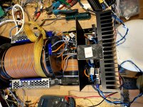
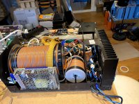
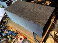
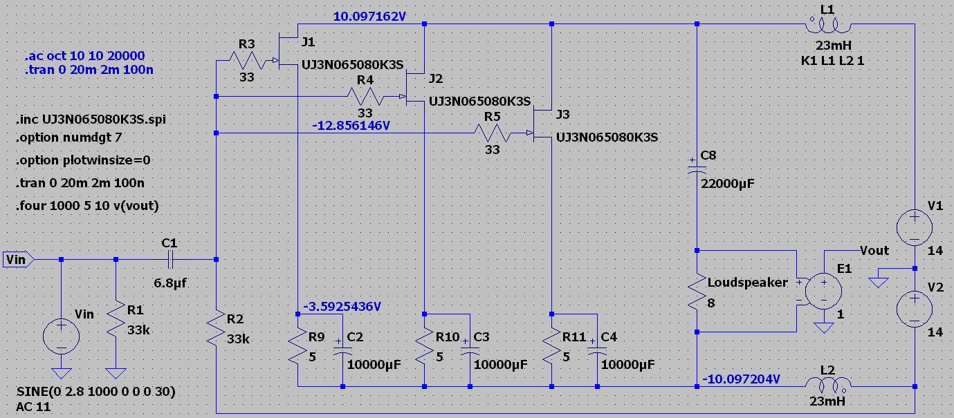
Made the SLAPS coils with iron core, put the whole thing into a box and put on a simple mesh metal cover.
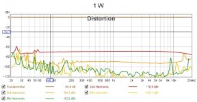
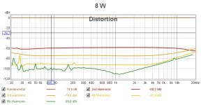
Included is also measurements with this SLAPS for SLAM! at 1 W and 8 W.
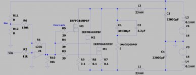
And the final schematic.
To investigate is the 3rd and 5th harmonic relative high distortion levels at 9 and 18 kHz.
Perhaps it is only a measurement system's artifact.
Three more SLAPS for SLAM! are built, just need to make the covers.
Then I can finally start to listen to music again.
Made the SLAPS coils with iron core, put the whole thing into a box and put on a simple mesh metal cover.
Included is also measurements with this SLAPS for SLAM! at 1 W and 8 W.
And the final schematic.
To investigate is the 3rd and 5th harmonic relative high distortion levels at 9 and 18 kHz.
Perhaps it is only a measurement system's artifact.
Three more SLAPS for SLAM! are built, just need to make the covers.
Then I can finally start to listen to music again.
Attachments
Last edited:
Final post then.
Well, that didn't last long
 .
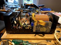
.I accidentally left two of them on for five or six hours and only noticed that by the smell of burnt plastic.
It turned out that one of the SLAPS coils had melted and was shorted.
Despite the close Vgs matching (3.889, 3.892 and 3.894 V), one of the MOSFETs had a not closed enough matched gain.
When getting hotter, it drifted and then failed to short circuit.
So matching has to be done in the actual amplifier (three MOSFETs).
That will be done measuring the voltage over the source resistors. Of course with a low bias first as a coarse matching.
Then by increasing the bias up to operating levels.
I will use an Arduino Nano, it has eight AD channels with 10 bit resolution.
The same Nano can be used to continuously monitor the voltages over the source resistors in a "live" amplifier.
It controls MOSFET switches between the power supply and the SLAPS coil and will disconnect the power should one or the sum of the voltages drift.
It can also monitor the temperature with an NTC resistor or a DS1820 or equivalent.
I need to check if the Nano makes any audible noise of course.
I am also considering an NTC resistor on the incoming AC to limit the inrush current so that the household's fuses doesn't trip.
It is getting more complicated but the amplifier's audio path will remain simple.
I saw that the inductance increased with a iron core when I worked with SLAPS for bass, and that the low frequency response improved.
You may be interested in the experience of Russian DIY er)
YouTube
YouTube
Phantom amplifier
https://radioskot.ru/_fr/155/0846069.pdf
Sergei Falkov uses a DIY transformer with a core of iron plates. Like Susanne Parker. The diagrams are clear.
Automatic translation of the text at your service.)
Apart from the output transformer leg, it is identical to the SLAPS.
Last edited:
SiC JFETs
I have now tested UJ3N065080K3S that I recently tested in the SLAPS for bass thread.
It's a silicone carbide depletion JFET that is normally on.
"Bias" is then adjusted by the source resistor.
I've found that 5 ohms gives the best result
Compariing measurement with the 044 (MOSFET):
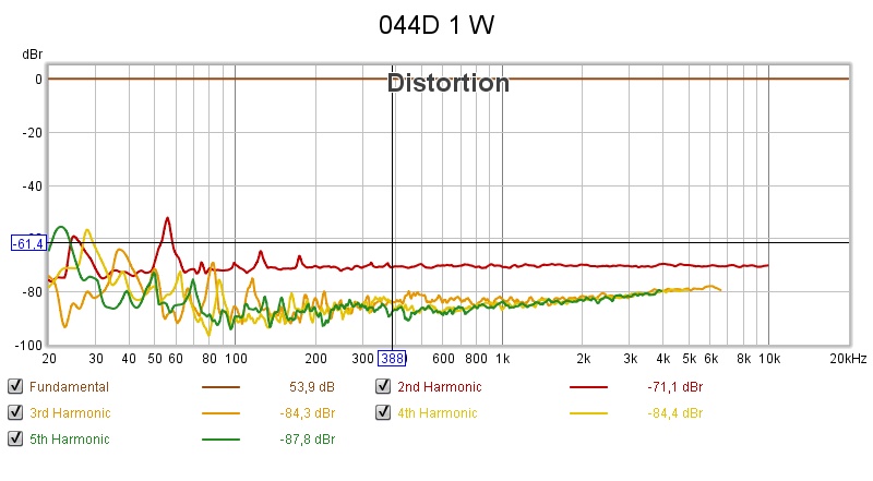
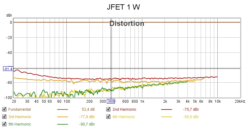
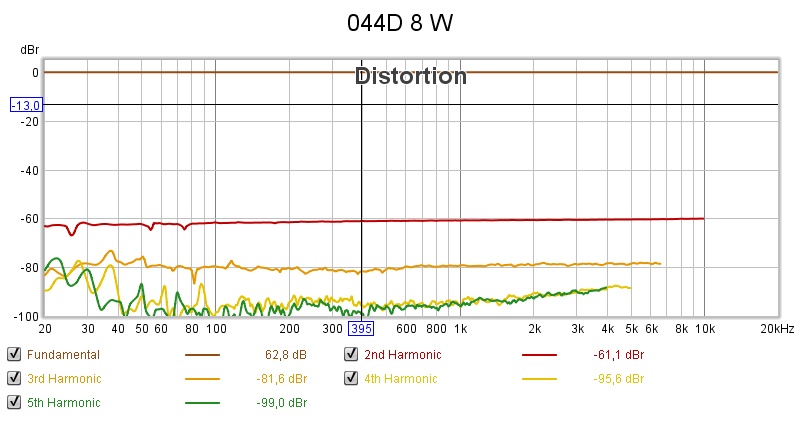
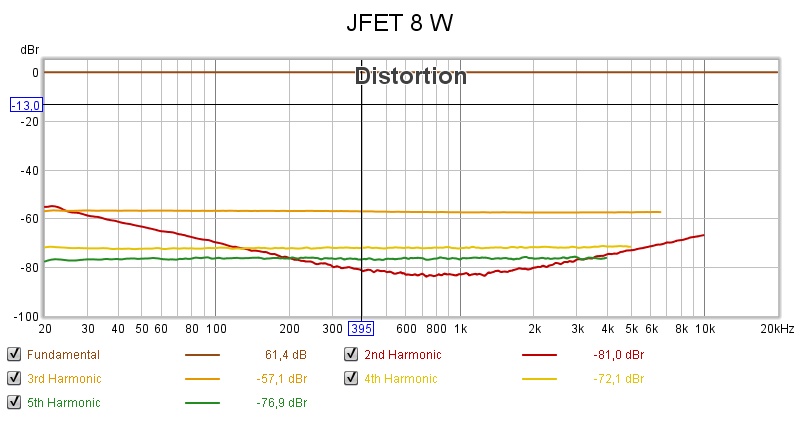
One can see that 2nd is much lower with the JFETs but also that the 3rd is higher and för 8 W even above 2nd.
For 4 W, which is the design target, I currently only have measurement for the JFET:
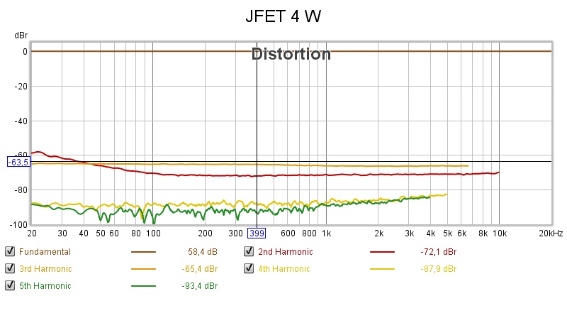
To me, the higher 3rd gives me some concern, it can "crash" at high volumes such as a high hat.
2nd should be sweater for the ear, so the higher levels with the 044 can perhaps be overseen.
Any other thoughts?
I have now tested UJ3N065080K3S that I recently tested in the SLAPS for bass thread.
It's a silicone carbide depletion JFET that is normally on.
"Bias" is then adjusted by the source resistor.
I've found that 5 ohms gives the best result
Compariing measurement with the 044 (MOSFET):
One can see that 2nd is much lower with the JFETs but also that the 3rd is higher and för 8 W even above 2nd.
For 4 W, which is the design target, I currently only have measurement for the JFET:
To me, the higher 3rd gives me some concern, it can "crash" at high volumes such as a high hat.
2nd should be sweater for the ear, so the higher levels with the 044 can perhaps be overseen.
Any other thoughts?
I would go for the IRFP044.
The SIC JFET seems to be very uneven and change its character much more dependent on frequency and output power level.
A frequency and output power dependent change is often much more detrimental to the sound quality and the enjoyment of music then slightly higher but stable non changing level of change in character.
That's quite a part. Never ceases to amaze me, some of the modern devices available. And for a pittance -- DigiKey sells 'em for US$6,90 !!
There are some real puzzles in those distortion graphs. Not sure even the golden-ear folks could discern the ratio of 2nd to 3rd harmonic on a Hi-Hat, though.
How on earth did you decide 3 of them was the correct number? (If/when you have time ..)
Regards
There are some real puzzles in those distortion graphs. Not sure even the golden-ear folks could discern the ratio of 2nd to 3rd harmonic on a Hi-Hat, though.
How on earth did you decide 3 of them was the correct number? (If/when you have time ..)
Regards
I would go for the IRFP044.
The SIC JFET seems to be very uneven and change its character much more dependent on frequency and output power level.
A frequency and output power dependent change is often much more detrimental to the sound quality and the enjoyment of music then slightly higher but stable non changing level of change in character.
Yes, that's my conclusion as well. I will get some more IRFP044s (and return the JFETs I just got) and try to match them better.
That's quite a part. Never ceases to amaze me, some of the modern devices available. And for a pittance -- DigiKey sells 'em for US$6,90 !!
There are some real puzzles in those distortion graphs. Not sure even the golden-ear folks could discern the ratio of 2nd to 3rd harmonic on a Hi-Hat, though.
I will go for the IRFP044 for the same reasons Circlomanen posted above.
The JFETs also required some more (too many!) components.
The only pluses I can see with the JFETs (the price is really of low interrest considering the cost of the other components and the time spent) are that they are easier to match and seems to be more stable than the MOSFETs.
How on earth did you decide 3 of them was the correct number? (If/when you have time ..)
Regards
I really wanted the transconductance of one, but at that resulting current (some 6A or so) it will not last long.
Having several at a lower bias will add up to that transconductance and thus share the current; the devices will last.
I still have to dissipate the same heat though.
Form factor: I wanted a heat sink as wide as the SLAPS coil and then three what was fitted in without heating each other and still effectively dissipating heat.
Perhaps it is one too many though.
Input capacitance of one (IRFP044) is 1.5 nF, so it'll add up and affect the frequency response.
I'm not sure though where the limit is though!
Perhaps four or more of them will measure better and the heat sink still can dissipate the heat (the current in each will lower) and the added input capacitance will not audible affect the frequency response.
I can at the least test a prototype with two heat sinks and six devices! (Thanks for the inspiration!)
By the way, "SLAPS for bass" is exactly that, but with IRFP150s instead as they have greater Vdss (100V) .
As it is a bass driver, the input capacitance (2.8 nF) is of lower interest.
- Status
- This old topic is closed. If you want to reopen this topic, contact a moderator using the "Report Post" button.
- Home
- Amplifiers
- Solid State
- SLAPS for SLAM!