Agree on all counts. I'm sticking to the power supply. What complicates things a bit is the lack of reference voltages in the service manual, though I know folks with more experience than me aren't reliant on knowing them (or can more quickly figure out what they should be).
I ask about B3 because I'm seeing 20V there.
I ask about B3 because I'm seeing 20V there.
It's a 21 V zener, followed by two B-E voltage drops or ~1.2-1.3 V less. Thus 20 V sounds about right.
The more interesting question is how stable it is.
You may still be dealing with bad joints on the regulator transistors (not at all uncommon due to thermal stress), one of them just being bad, or an intermittently shorting capacitor (while C909 and C910 basically are adequately sized, you just never know after 40 years).
Thanks. Regarding the stability of the B3 voltage, I watched it for about 15-20 minutes, and it fluctuated by 300-400 mV during the first 5 minutes after power on. So it went from 19.8V down to as low as 19.4V, before settling back at 19.8.
Also, for what's it's worth, I'm seeing between 200-300 mV at the main in/pre out jumpers.
Also, for what's it's worth, I'm seeing between 200-300 mV at the main in/pre out jumpers.
Last edited:
Thanks. Regarding the stability of the B3 voltage, I watched it for about 15-20 minutes, and it fluctuated by 300-400 mV during the first 5 minutes after power on. So it went from 19.8V down to as low as 19.4V, before settling back at 19.8.
Also, for what's it's worth, I'm seeing between 200-300 mV at the main in/pre out jumpers.
You shouldn't have ANY DC voltage on the pre/amp jacks (with no signal, volume turned off).
Must be leaking coupling caps to/from those jacks.
Do note that there aren't any pull-down resistors at the pre output, so if you pull the jumpers to measure and the meter's input impedance (at least 1 and commonly around 10 megohms more often than not) is the entire load, I would expect some DC... now if this is with the jumpers still in, well, yes, that would be rather leaky caps indeed. Not like this would be a huge surprise or anything.
I would suggest measuring where power amp input ground is on R602 - just in case.
Hmm, they have a 220µ/6.3V input cap on the power amp input - like, seriously? Opposite polarity to the preamp 10µ as well. (a) I wouldn't trust any 40-year-old 6.3 V cap, and (b) a leaky 10µ might well mean that this gets reverse-biased (desiab-esrever). Two caps back-to-back is a neat trick and all (effectively gets you a bipolar and reduces distortion), but two very different ones, I dunno...
This may require measuring on R602/622 now, since the potential on the pre-power bridges is essentially floating.
Not really sure how to fix this long-term. Maybe find some less silly 47µ/25-50V part for the power input and get the pre out a pull-down R in the low hundreds of kOhms. Or just use identical caps on both sides... 10-22µ should be big enough, really.
Thanks sgrossklass Yes, I had noticed that the voltage was significantly higher at the pre outs with the jumpers pulled and was wondering why. I appreciate the explanation. But with them in, I'm actually seeing 500mV in one channel and 300mV in the other.
R602 and R622 show zero volts on the amp input ground side.
I'm going to start by swapping out the two 10uF caps at the output of the tone board and see where those voltages at the pre out are after that.
R602 and R622 show zero volts on the amp input ground side.
I'm going to start by swapping out the two 10uF caps at the output of the tone board and see where those voltages at the pre out are after that.
Last edited:
On the desk I have currently a device of this model, where it is exactly the opposite - also to observe in front of the stereo decoder with MC1307. This means, only the RF-unit and IF unit create this deficiency. Popping is only temporary present and in low level mode (audible during pauses in speaking). In the attachment are images of the IF amplifier without screen cover, and resistors in the kind as to find in the images from post #23 underThe old HK receivers of this era have problems with the preamp sections due to caps, switches.
The tuner and power amp sections often still work great, though.
https://www.diyaudio.com/community/threads/harman-kardon-930-bias-adjust.239812/page-2
- known for issues in such kind - are not in use on this IF PCB.
Which parts should I replace first? Ceramic caps, germanium diodes, dual ceramic filter or IF amplifier ICs ?
Thank you very much for an advice.
Attachments
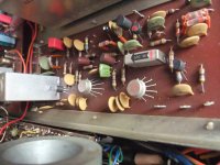
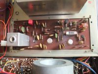
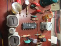
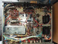
Unless you've got the mandatory test equipment and experience to do a complete alignment of the IF and stereo multiplex boards, I'd recommend you leave those ceramics, diodes, filters alone.On the desk I have currently a device of this model, where it is exactly the opposite - also to observe in front of the stereo decoder with MC1307. This means, only the RF-unit and IF unit create this deficiency. Popping is only temporary present and in low level mode (audible during pauses in speaking). In the attachment are images of the IF amplifier without screen cover, and resistors in the kind as to find in the images from post #23 under
https://www.diyaudio.com/community/threads/harman-kardon-930-bias-adjust.239812/page-2
- known for issues in such kind - are not in use on this IF PCB.
Which parts should I replace first? Ceramic caps, germanium diodes, dual ceramic filter or IF amplifier ICs ?
Thank you very much for an advice.
Start by troubleshooting and monitoring voltages in those circuits, perhaps a funky electrolytic is the cause, or maybe a resistor that got noisy.
An o'scope and RF generator is another required piece of equipment when dealing with critical tuner issues.
An other device of this model seems to be the best solution, because then I can change the 10,7MHz IF board and do observe, if this unwanted effect also change to the second device or not. If yes, after this task I change the parts step by step on the IF PCB's until the effect is walking again to the PCB in perfect working condition.Unless you've got the mandatory test equipment and experience to do a complete alignment of the IF and stereo multiplex boards, I'd recommend you leave those ceramics, diodes, filters alone.
Start by troubleshooting and monitoring voltages in those circuits, perhaps a funky electrolytic is the cause, or maybe a resistor that got noisy.
An o'scope and RF generator is another required piece of equipment when dealing with critical tuner issues.
An other device of this model seems to be the best solution, because then I can change the 10,7MHz IF board at first step and do observe, if this unwanted effect also change to the second device or not. If yes, after this task I change the parts step by step on the IF PCB's until the effect is walking again to the PCB in perfect working condition.
- Home
- Amplifiers
- Solid State
- Harman Kardon HK 930 popping noise troubleshooting