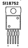
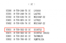
There are two picks from the Sony STR D-615 service manual to help in my question. My receiver (Sony STR-D615) started blinking "protect" after a power outage. The outage actually fried the surge protector the receiver was plugged into. I have never tested a transistor for short such as the one in the pics which has 5 terminals. I tested all of the transistors on the heat sink besides this one as they all have only 3 terminals. They all tested OK (at least not short). I would like to know precisely how to use my multimeter to check the one in the pics below...
Edit: I am a kit builder at best and can follow simple instructions but beyond that I have no training. I am tinkering because this unit is probably not worth the cost of repair unless I can do it myself.
Edit: I am a kit builder at best and can follow simple instructions but beyond that I have no training. I am tinkering because this unit is probably not worth the cost of repair unless I can do it myself.
Attachments
Last edited:
http://www.datasheetcafe.com/wp-content/uploads/2015/10/SK18752-Datasheet.gif
An example of the application of a similar chip ...
An example of the application of a similar chip ...
I am not sure, but could this below be a possible candidate for a replacement chip?
(PDF) LM1875 datasheet PDF file
(PDF) LM1875 datasheet PDF file
zjjwwa thank you for the response. Unfortunately the link looks like a foreign language to me. I am a kit builder at best and can follow simple instructions but beyond that I have no training. I am tinkering because this unit is probably not worth the cost of repair unless I can do it myself.
OK, let me say it simpler. Look at the pictures there.zjjwwa thank you for the response. Unfortunately the link looks like a foreign language to me. I am a kit builder at best and can follow simple instructions but beyond that I have no training. I am tinkering because this unit is probably not worth the cost of repair unless I can do it myself.
The chip that you are referring to is most probably not a simple "transistor", but an integrated "Operational Power Amplifier", with 5 pins.
Or in other words, a complete power amplifier within a chip.
If I understand correctly, the pins are numbered as follows:
1: The non-inverting input of the operational amplifier
2: The inverting input of the operational amplifier
3: the MINUS supply voltage as delivered to the chip
4: the OUTPUT (to speaker) of the chip
5: the PLUS supply voltage as delivered to the chip.
If I were to guess, I would check if there is a short between the legs 5 (positive power supply) and 3 (negative power supply). If this is close to zero ohms, I would suspect a serious problem with the chip.
If between 5--3 you do not observe a problem, then ...
Then I would check if there is a short between any of the power supply legs (5, 3), and the output of the chip, the output that goes towards the speaker. If you observe a very low resistance between 3==>4
and/OR
4==>5 ,
I would suspect that one of the output transistors within the chip is fried short.
If you do not see evidence of a short between 3==>5, or 3==>4, or 4==>5, then I would maintain hope that the chip is intact.
These are just WAG musings of a non-professional. Hope this helps.
Then, I would probably
Last edited:
here is an example of an auction service, where the cost of a similar (hopefully) "replacement" chip is just under two US dollars.
The price of the postage stamp will outweigh the price of the chip.
LM1875 SCALONY WZMACNIACZ MOCY 7711638080 - Allegro.pl
Please consult with other, more experienced DIY'ers, if this suggested LM1875 is a suitable replacement for the chip that you have listed in post #1.
The price of the postage stamp will outweigh the price of the chip.
LM1875 SCALONY WZMACNIACZ MOCY 7711638080 - Allegro.pl
Please consult with other, more experienced DIY'ers, if this suggested LM1875 is a suitable replacement for the chip that you have listed in post #1.
This Sanken chip seems to cross to LM1875 or TDA2030A, medium power chip amps. The above links will give you the pinout and everything. It's +in, -in, -V, out, +V.
If the chip is still installed, the first thing I would do is check the DC voltage at R659, R658 or L651 vs. ground (use chassis or speaker (-) if nothing else) when powered up. Something in the millivolts is good, more than 0.5 V in either direction is bad and would indicate that the chip is indeed faulty. Follow the pin 4 connection to the Rear output if you don't know where these components are.
You could also measure the voltage across C653. If it's more than a few mV, something's really amiss.
If you can't get the unit to stay on long enough for a measurement, you could test for shorts between pins 4 and either 5 or 3 when powered off. Even if that turns out good, the chip could still be damaged in other ways. Temporarily unsolder one end of R660 to see whether that clears the fault. (You should have removed any speakers by this point for obvious reasons.) If so, bad chip. Otherwise, it's another power amp give you trouble.
If you need a replacement, LM1875Ts are still being made, it just seems to be a good idea to buy them from trusted distributors (Mouser, Digikey etc.) rather than random Chinese eBay sellers, as counterfeits abound.
Your power outage had to have involved substantial overvoltage if the surge protector got blown. Was the unit powered on at the time? If so, any of the power amps could have taken damage from overvoltage. Otherwise I'd be more inclined to look in the power supply area for any supply voltages that may be missing or low.
Probably. See what it says in ohms and in the diode test setting.
Is the chip still soldered in? Unsolder pin 4 and verify that the short is actually in the chip and not external. If so, yep, he's dead, Jim. Replacement options have already been discussed.
Do you have some thermal compound? You need the plain white silicone-based stuff. Thermal paste for PC use can be conductive, which is not what you want in a power amp application.
Oh, here's a potential snag - the old part looks like it may have an insulated tab, so it might be mounted directly to the heatsink. The new part (which definitely does not have that kind of luxury) should be mounted using either a matching Silpad or preferably a mica washer with a bit of thermal compound on both sides. TO220-5 should bring up the right size.
Should the old part already be using a mica washer (careful - they are very thin and brittle), you can clean it up and reuse it. You can use either isopropyl alcohol or white spirit / naphta or similar to clean the surfaces.
The screw going through the tab also needs some sort of insulating washer.
Last edited:
- Status
- This old topic is closed. If you want to reopen this topic, contact a moderator using the "Report Post" button.
- Home
- Amplifiers
- Solid State
- How can I test this transistor for short?