Well I have great succes by opgrading the output transistors in my Quad 303 ")
Has anybody tried new output transistors for a Quad 405 or a Quad 405-2 ??
I'm curious because I heard that the current dumping technology which 405 uses, makes it critical how fast the output transistors are
Best Regards, Ask
Has anybody tried new output transistors for a Quad 405 or a Quad 405-2 ??
I'm curious because I heard that the current dumping technology which 405 uses, makes it critical how fast the output transistors are
Best Regards, Ask
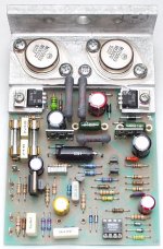
Here is the QUAD 504.2 UPGRADE
http://www.net-audio.co.uk/quad405caps.html
http://www.net-audio.co.uk/quad405caps.html
Attachments
Yes I know how to change opamps, capasitors and resistors on my 405,2 which I've done with succes
But how about the output transistors??
I'm thinking of what I read in:
http://www.dc-daylight.ltd.uk/Valve-Audio-Interest/QUAD/QUAD-405/QUAD-405-Mods.html
http://www.dc-daylight.ltd.uk/Valve-Audio-Interest/QUAD/QUAD-405/405_Qw_6.pdf
405_Qw_6.pdf page 8 quote:
b) The following modifications are without any(!) benefit as long as speakerimpedance doesn t drop significantly below 4 Ohm (and even in that case the audibility is debatable, of course). Usually the 405 is not recommended for this kind of low-impedance-loads -- but have a look ... I did this mod for curiosity-reasons only, and it works nicely indeed. But it requires some 'hard work' and is a pleasure only to her (or him) who enjoys opening the toolbox (purists should skip the rest of this section to avoid heart-attack!).
To get more current with less distortion, you can upgrade each single outputtransistor (17556, 2SD424 -- or even the veteran BDY77) by a pair (yes: a pair!) of up-to-date-devices. Doubling the devices will give safer and better performance with low-impedance loads because each device will work at half the current (where their current-gain is higher) and resistive losses are reduced as well. Thanks to the uncritical class-C design of the dumper-stage (no quiescent current) this upgrade is no problem electrically (as the 606-family shows). Mechanically it has become rather easy thanks to the new TO-3P(L)/TO-264 'plastic'-packages for powersemiconductors.
A state-of-the-art choice for upgrading might be Toshiba's recent 2SC5200 (or 2SC5359) which replaced the recommended 2SC3281 in ~1997 (be careful: by now most devices offered as Toshiba 2SC3281 are just fakes - something like 2N3055s in TO-264-cases!). Motorola's improved copy, MJL3281A, seems to be still in production, and recently ON-Semiconductors introduced the MJL4281A. They all have nearly constant dc-current-gain of about 100 from 10mA up to ~7A (with the older types gain drops from about 50 at 3A to less than 30). But unfortunately they are very fast (CGBP ~30Mhz) and thus not wholly uncritical. There is no benefit from increased dumper-speed here, on the contrary: if the dumpers open too fast, the class-A stage may be too slow (due to C8) to react in time. Test for overshot with 1kHz square-wave. Usually ~1nF (ceramic) from collector to base of Tr10 (like C19 in some issues of the 405-1) will help already. (If you are lucky, C19 and R41/L3 are present on your board [sn. 9000 to 59000]; this will put you onto the safe-side anyway).
Motorola's MJL21194 and 21196 (a kind of improved 15024) are more conservative alternatives: They are not that fast (CGBP ~7MHz) and they show nice current-gain characteristics up to 5A as well (which is, obviously, more than ample, at least with double-output-devices). 'MJ' indicates TO-3 at Motorola, 'MJL' is TO-3P(L)/TO-264, so look for the 'L' here, since all are available in 'classical' TO-3 as well. Maybe even some TO264-versions of MJ15003 are (or will be) available.
unquote
Best regards, Ask
Mac Mod (Steve McCormack) mods to Quad 405
Hi!
And thanks for keeping this Quad 405 thread alive
At:
http://www.quadesl.org/Amplifiers/body_amplifiers.html
I read:
Quote
MAC MOD 405 USA
...
- Current Limiting removed
- Improved IC fitted (LM 318)
- Faster Drivers ( Motorola MJE 15031 )
- Faster Output Devices ( Motorola 2N3773 )
- Improved Resistors (metal-film 1% by Resista Mk3 or Corning RN-60 )
- Improved Capacitors (Wonder Caps, Wima, dipped mica)
- Improved Wiring (Audioquest) and Plugs (Tiffany)
UnQuote
I just wondered if anybody tried something even faster?
Regards, Ask
I have used 2N5038s in place of the MJ16003s in the past and they have an Ft of 60Mhz. I could not tell any difference. I was wondering if anyone had tried altering the value of the 560r bootstrap resistors to increase the contribution of the class A amp. When using MJ15003s I also increase the capacitors that determine time constant for the current limit to 100uF makes a small improvment and so far I have had no problems.
I agree MJ15003's are a good transistor for the 405
The 405 has been very popular. Its low distortion is
remarkable. This asset endears the amp to many
listeners. Very few amps manage to get this low
in distortion
On the interesting side
the use of capacitor inductor and resistors in the bridge
circuit has invited lots of discussion asking whether these
components combine properly. The distortion figures
and actual use suggest they are very well chosen for
consumer use. Other values however have been tested
to see if distortion can be lowered further,but not necessarily suiting consumer use.
Cheers / Chris
Change 405 output transistors:
Why bother, the output dumpers are not the problem, most of the questions asked in this thread specifically the bridge arrangement are answered at:
http://www.dc-daylight.ltd.uk/Valve-Audio-Interest/QUAD/QUAD-405-Modification/QUAD-405-Mods.html
note: this URL has changed from that above.
Why bother, the output dumpers are not the problem, most of the questions asked in this thread specifically the bridge arrangement are answered at:
http://www.dc-daylight.ltd.uk/Valve-Audio-Interest/QUAD/QUAD-405-Modification/QUAD-405-Mods.html
note: this URL has changed from that above.
I agree MJ15003 as specified by Quad are fine
I have read the article you refer to , and I recall
doing extensive article research into the bridge
arrangement in the 1980's.
If you can source Electronics World for 1976, 77 and 78
there was fierce disscussion almost bordering on law
suits in that journal. I remember most of the discussion
centered around R12 and C6 where the articles
contributor insisted they were not needed, and
that contributor even went so far as suggesting the
current dumping design was not valid. !!! .. um
I remember Vanderkooy and Lipitchz came to the
rescue and published results affirming Quads excellent
design and just to prove the point measured a stock
405 finding very good results for a consumer product.
They went on if I recall correctly, to seek absolute perfection
suggested modifications to the bridge, where
trimming of R20 and R21 for better tolerance ,
was suggested with near perfect results, but not
necessarily suiting consumer use... and once again
by that, affirming Quads values as excellent for general
use.
It is a long time since I have studied opamp parameters
so apologies if Im a bit out of date. I find with these
forums because we are discussing real physics terms
there is not much allowance if you say something wrong.
Ill try my best in any case.
Ive been looking at the input redesign, provided
in the link and comment Quads design has a defined
summing point at the junction of R3 and R4 with
the opamp driven inverted , and from what I can determine
to then sum the feedback and input with stability
in mind.
The redesign offers different frequency
shaping referring to C4 and is positive input loaded
I have not tried this change, but could it invite
positive feedback oscillation?. Im sure the values
chosen have adequately taken this into consideration.
One technique that may also be a solution for input
noise, and suggested not for this design at all, but in
CD circuits ( see Supertuning Cd Nov 1987 Hi Fi News )
from Ben Duncan ,is to lift the + input.
which enables the opamp discussing CD circuits to ..
as Ben puts it "calm down"
Whether this too invites instability in the Quad 405
I have not determined ... but nevertheless is a very simple modification and works ( at about 330ohms ) to sound very
good in the Quad circuit.
A Quad 405 with such a ground lift on the positive input
is silent into ESL57's , as is a standard Quad 303.
Cheers/ Chris
Firstly QUAD whoever they are now developed on the bridge arrangement and so was born the 306, 606 ....
Do you mean Wireless World, I have virtually all of them from 1953 to 1984 when it became "Digital World" and yes the arguments went on, I however was more interested in listening to music on my old QUAD IIs and getting music to the people through the medium of radio.
Trimming R anything will not reduce all distortions while the Bridge topology is incorrectly applied albeit to due to the practicle application of available semiconductors at the time. While TR1 remains upsetting the bridge any adjustment will be limited to a specific set of conditions and not frequency or level independant.
Unless the op-amps are changed for "OPMAXADs" why should non inverting be potentially less stable than inverting. You say "could it invite positive feedback oscillation?" how would this occur, a slight reduction of hf common mode rejection but unstable ??
As for C4 being changed in the article it is clearly mentioned that it is scaled to the gain reduction (0.5x) to restore the original high pass response and this it does correctly. if the gain is not reduced (see downloaded pdf) the value of C4 remains the same.
I am sure that a man of Ben Duncans talents who SPICE models loudspeaker cables would soon tell you that the changes are OK, I hope they are because I have applied them to my 405 with amazing effect both measured and subjective, the only other amps of this eara to come close, IN MY OPINION are the Crimson electric modules, where are they now ?
I am not too sure what you mean by "lift the + input" and I do not intend to read an article entitled "Supertuning" same way I won't buy Hi-Fi from people who call themselves the "Good guys" (USA Store) or anyone at the beach. If it entails applying a small voltage at the + input then DON'T as this sets the output terminal offset and after modifying my QUAD 405 this was less than before I started at 0.7mV each channel.
If it means rather than connect the + input directly to signal ground (also 0V in the QUAD 405 case) connect it through a resistor then it is a good thing. if applied correctly this can reduce the effects of input bias in dc amps and could statistically reduce the noise at the output by introducing "ANTI NOISE" at + input to cancel out that at the - input, Oh my look at the DC-daylight article again, R3 "lifts" the + input and its the same value as the new R6, I also used same type for both so let the magic do it's stuff.
If you have a 405 and some test gear why not try the input mod it can always be put back easily if you find it unstable, if it is unstable please let me know !!
developed on the bridge arrangement and so was born the 306, 606 ....Do you mean Wireless World, I have virtually all of them from 1953 to 1984 when it became "Digital World" and yes the arguments went on, I however was more interested in listening to music on my old QUAD IIs and getting music to the people through the medium of radio.
Trimming R anything will not reduce all distortions while the Bridge topology is incorrectly applied albeit to due to the practicle application of available semiconductors at the time. While TR1 remains upsetting the bridge any adjustment will be limited to a specific set of conditions and not frequency or level independant.
Unless the op-amps are changed for "OPMAXADs" why should non inverting be potentially less stable than inverting. You say "could it invite positive feedback oscillation?" how would this occur, a slight reduction of hf common mode rejection but unstable ??
As for C4 being changed in the article it is clearly mentioned that it is scaled to the gain reduction (0.5x) to restore the original high pass response and this it does correctly. if the gain is not reduced (see downloaded pdf) the value of C4 remains the same.
I am sure that a man of Ben Duncans talents who SPICE models loudspeaker cables would soon tell you that the changes are OK, I hope they are because I have applied them to my 405 with amazing effect both measured and subjective, the only other amps of this eara to come close, IN MY OPINION are the Crimson electric modules, where are they now ?
I am not too sure what you mean by "lift the + input" and I do not intend to read an article entitled "Supertuning" same way I won't buy Hi-Fi from people who call themselves the "Good guys" (USA Store) or anyone at the beach. If it entails applying a small voltage at the + input then DON'T as this sets the output terminal offset and after modifying my QUAD 405 this was less than before I started at 0.7mV each channel.
If it means rather than connect the + input directly to signal ground (also 0V in the QUAD 405 case) connect it through a resistor then it is a good thing. if applied correctly this can reduce the effects of input bias in dc amps and could statistically reduce the noise at the output by introducing "ANTI NOISE" at + input to cancel out that at the - input, Oh my look at the DC-daylight article again, R3 "lifts" the + input and its the same value as the new R6, I also used same type for both so let the magic do it's stuff.
If you have a 405 and some test gear why not try the input mod it can always be put back easily if you find it unstable, if it is unstable please let me know !!
Lubbie
www.geocities.com/ResearchTriangle/ Lab/6722/quad405cir.html
Blue
Ive typed up some reasons why + feedback and oscillation
was mentioned in my previous post
The reasons for Quad using a summing point at the
junction of R3 and R4 and an inverting configuration op amp
is a clever use of applying negative feedback
Lets look at what is happening to that ? Looking at the circuit diagram the junction of R10 and R12 would tell us the difference between the input signals has enabled a corresponding output at
the opamps output, Lets follow this through.. The input is positive
the output of the opamp is negative, the emitter of TR2 is
then negative with respect to the input ie no phase change
after R10. the collector is +Dc and positive signal same phase
as the input and via C8 forms part of the bridge arrangement.
So an amplified negative signal with respect to the input
negative feedback returns to the summing point of the opamp
via the bridge network involving the emitter of TR2 , R5 and R4.
My prior post advocated a 330ohm resistor as ground lift for
the positive input of the opamp to reduce noise eminating from
IC1 and indeed a small voltage would then appear as offset.
In actual use this ground lift of the positive input of the opamp
does lower noise level.
Referring to Quads schematic Issue 9and 10 M12368 pin 6
has 1.7volts here in any case.Output offset appears not to be an
issue as such in Quads design, in fact may be encouraged as bias
for TR2. Possibly a fixed, or self biasing stage would be an
improvement here rather than the base of TR2 living in an unsure
world of DC offset emminating from IC1 , but then again is this part of Quads design to have opamp offset providing the bias for TR2.. it certainly looks like this.. where is this transistors base bias otherwise ?
R12 and C6 is a time constant network also aiding stability from what I can see, despite comments in Wireless World
If we look at the links post regarding rearranging IC1 as a
non inverting stage.. this then gets interesting.. Im not saying it
doesnt work as the page appears well presented and measurements attributing the change have shown improvement.
IC1 appears as placed in a very responsible role in this implementation it is again responding to differences between inputs gain would appear to be applied overall from both signal arriving at the + input and the negative input receiving feedback
but the question in my mind is that there is risk of postive feedback returning following the phases through the emitter of TR2 then is + identical to the input so positive feedback must arrive at the - input of the opamp which then busily responds to this added input. Can you see the the point I was making about possibility of oscillation ??
Then again if Quads bridge arrangement holds up TR2's collector
in a circuit with a positive input driven opamp is also
processing a negative signal , so this might be why your
implementation works .. it is sort of forcing the bridge to
consider an alternate path.... this is getting a bit beyond my
understanding
I would be interested in your comments, but from what I can tell
stability may be compromised
Possibly the values of C1=C4 and R3 =R6 are the controlling elements stopping a positive oscillation if one exists getting
out of hand. The other possibility is the bridge arrangement is differently implemented by a positive input opamp and negative feedback arrives at R5 regardless of the phase on the emitter
of TR2.
Cheers / Chris
Chris
This appears to have become a Ping-Pong match between us so please forgive me if I put down my bat after this hit. I made the original comment because I saw the dc-daylight article Bernd Ludwigs articles between them providing most of the answers to the thread as I read it, I did not want to kick the hornets nest although I believe I am well within my depth on this subject and not getting stung or up a gum tree without a paddle ?
"My prior post advocated a 330ohm resistor as ground lift for
the ....."
Why not a 360R or 390R or 430R or... these low values do nothing compared to the complete topology change ?
"Referring to Quads schematic Issue 9and 10 M12368 pin 6
has 1.7volts here in any case.Output offset appears not to be an
issue as such in Quads design....
The output offset referred to is the offset at the speaker terminals and takes into account the dc gain of IC1 working "flat out" and the 3.78x gain of the class A and dumper stage which have to be dc coupled.
Thus IC1 is not simply biasing Tr2 it is setting the dc conditions of all that follows and the terminal output offset is referenced to the voltage at its – input plus/minus any imperfections it has. When I applied the mod I was concerned that LF stability may be upset but after analysing it and actually building and measuring it I could find no problems at all.
"R12 and C6 is a time constant network also aiding stability from what I can see, despite comments in Wireless World"
I think as stated in the article (which quotes P walker from WW) it is to reduce TID (TIM if you wish) even if it was not originally viewed as such this is what it does. IC1 and the dumper stage are working independently at the high frequencies of the R12/C6 combination so it cannot be "aiding stability" of either section of the amplifier
"If we look at the links post regarding rearranging IC1 as a
non inverting stage.. this then gets interesting.. Im not saying it
doesnt work……."
I believe it does work but only because I have built it and tested it but more importantly listened to it over a period of about 2 months now and it sounds great, even with the current limiters still in place.
"IC1 appears as placed in a very responsible role in this implementation……"
This is an understatement! Forget following phases around the circuit "IC1 performs several roles" as the article states but in the audio band it acts completely separate from the Class A plus dumper stage and at dc it performs exactly the same in either topology.
Note that the 606 uses an op-amp only to control the dc offset and the signal path is all bipolar transistors.
I was concerned about what happened between dc and say 20Hz but if there is a problem with the mod in this area I think my test gear would have picked it up and I would be picking up glass from my broken windows along with bits of speaker cone.
"Possibly the values of C1=C4 and R3 =R6 are the controlling elements stopping a positive oscillation if one exists……"
I doubt very much that they are. I know I alluded to the "magic" of having them the same value and type which is potentially more voodoo (a local hobby we have) than science although there is something in it, same way polystyrene capacitors make any audio component sound better. OK I’m treading on thin ice, but trust me on the polystyrene caps.
After the mod my 405 had distortion at 1kHz (30W) of –96dB and at 10kHz –70dB (C8/L1 could be adjusted?) the noise floor ref. 30W was about –105dB but more impressive was the perceived noise at low level listening.
One last thing I did not do which could be revealing… Following the mod the amplifier is non inverting. Why not reverse your speaker terminals for a while to see what effect it has, I may do the same to see if it is a contributing factor to the improved sound. If you then apply the mod and listen with the speakers "normal"…….
OK Love all, lets play on
Some Questions about 40872
Hi everyone: I just did some mods to my later Quad 405-2 amp... but I encountered some situations:
1. I changed output transistors from RCA17556 to On-Semi MJ21194G---nothing unusual, everything works perfectly.
2. Then I changed the upper driver from RCA40872 to On-Semi MJE15033G---BIG PROBLEM! this stage creates hissing sound, and on my Tek scope, it shows a noise on its collector, base about 500 mV p-p.
3. Then I tried some other mid-power transistors with narrower GBP like TIP-42C: 405-2 is back to normal again!
Anyone has any idea about where this noise is coming?! Parasitic oscillation?! I have to confess: Mr. Ludwig said there is no use to upgrade the upper driver, but on the other hand, lots of people seem to modified the upper driver to MJE15033 without any problems.
- Home
- Amplifiers
- Solid State
- New Output Transistors for a QUAD 405 (2)