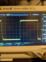
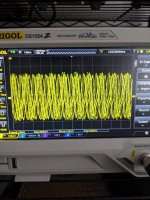
Attached is a picture of the square wave test I just performed, and the schematic.
I have a compensating 100 pF cap across the VAS stage.
Before testing, I removed the 33 pF at the input of the differential pair to be able to see oscillations above it's rolloff.
Should I be wary of this square wave response? There seems to be a little bit of overshoot and a some ringing present as well.
Thanks
Attachments
That amount of ringing would make me nervous.
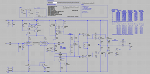
I'm not sure if I'm seeing the schematic correctly...it's a bit fuzzy...but I think that the whistle-stop resistors in series with the bases of the output transistors are, at 22 Ohms, too large. (please ignore this comment if they are actually 2.2 Ohms)
I'm not sure if I'm seeing the schematic correctly...it's a bit fuzzy...but I think that the whistle-stop resistors in series with the bases of the output transistors are, at 22 Ohms, too large. (please ignore this comment if they are actually 2.2 Ohms)
2x MPSA56 = ~18 pF of Cob at ~-29 V. Try some single-digit pF across R28 to compensate.
The input stage is a bit weird in general.
4 mA of tail current? Isn't that a bit excessive? I vaguely recall that higher input LTP tail current didn't exactly make my life easier in sim.
You could afford higher values of R3/4, reducing current mirror noise. Try 220 ohms or so.
If MPSA56 have too much Rbb' for your liking, I would rather pick a different transistor with more beneficial characteristics than parallel two. With the given values of R25/R28, you don't benefit from it anyway (too high). For starters, try only one 2N5087, at maybe 1 mA of tail current, 2 mA tops. That should push your Cob under the 2 pF mark.
I think it is a very good wave signal response , because it 's very fast .
All amplifiers show this type of response with a faster signal than they can handle.
With a low-pass filter at input and you'll see it correct.
BR
That is the way I see it too - the rise time of a square wave, being inversely proportionate to frequency, is a lot higher than the nominal 10kHz.
One can calculate the slew rate taking the peak voltage in combination with the rise time. You can work out the capability of your amplifier by simulation and filter the input signal to suit. Try to keep the input series resistance low for RC calculations.
Try adding some capacitive loading on the output (upto 1µF) and see if it then oscillates (limit the supply current to avoid destructive power levels) - that would be proof of instability.
This might be a case for adding a small cap between VAS out and negative rail, 10pF to 33pF
perhaps.
This might be a case for adding a small cap between VAS out and negative rail, 10pF to 33pF
perhaps.
Those are 22 ohm base stoppers. Should they be lower?That amount of ringing would make me nervous.
I'm not sure if I'm seeing the schematic correctly...it's a bit fuzzy...but I think that the whistle-stop resistors in series with the bases of the output transistors are, at 22 Ohms, too large. (please ignore this comment if they are actually 2.2 Ohms)
I've done both tests with unloaded and purely resistive 8 ohm load.What load are you using? A speaker with some longitude of wires, or a non inductive resistor with short wires to the amp?
I'll get that posted in the main post, or this one.it looks like to have compensation issue.
Please post your asc file and models to try to help based in your simulation.
I'll take this advice into consideration, thanks.2x MPSA56 = ~18 pF of Cob at ~-29 V. Try some single-digit pF across R28 to compensate.
The input stage is a bit weird in general.
4 mA of tail current? Isn't that a bit excessive? I vaguely recall that higher input LTP tail current didn't exactly make my life easier in sim.
You could afford higher values of R3/4, reducing current mirror noise. Try 220 ohms or so.
If MPSA56 have too much Rbb' for your liking, I would rather pick a different transistor with more beneficial characteristics than parallel two. With the given values of R25/R28, you don't benefit from it anyway (too high). For starters, try only one 2N5087, at maybe 1 mA of tail current, 2 mA tops. That should push your Cob under the 2 pF mark.
SO maybe the input cap is necessary. Might take Mark Tillotson's advice and current limit and add 1 uF across output, see if it oscillates.That is the way I see it too - the rise time of a square wave, being inversely proportionate to frequency, is a lot higher than the nominal 10kHz.
One can calculate the slew rate taking the peak voltage in combination with the rise time. You can work out the capability of your amplifier by simulation and filter the input signal to suit. Try to keep the input series resistance low for RC calculations.
Very interesting. This could be a quick way, hopefully nondestructive, to test if I'm oscillating or not. ThanksTry adding some capacitive loading on the output (upto 1µF) and see if it then oscillates (limit the supply current to avoid destructive power levels) - that would be proof of instability.
This might be a case for adding a small cap between VAS out and negative rail, 10pF to 33pF
perhaps.
I could try adding a cap there for compensation. ThanksA cap is missing over R28 feedback resistor...use the one removed from input for test purpose and measure again.
Attachments
Last edited:
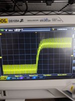
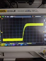
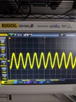
Tests conducted
I conducted a series of tests:
1. 50 mVpp square wave, input cap added, no load
2. 50 mVpp square wave, no load
3. Input attached, not on, no load
4. No load, no input
Those four tests are in the pictures. (they uploaded in reverse order, so read 4->1 in testing order)
In terms of compensation, here are the notes I took:
1. Cap across output (0.1 uF), immediately current limit, set to 600 mA but I don't think I wanted anything higher, it was definitely oscillating
2. Cap across feedback resistor, immediately current limit as well.
I definitely think I have a compensation problem.
Attachments
The circuit is marginally stable, and an input filter will not change that.
We don't know the filter has been implemented. I think that is the first step but the Miller capacitor comes into consideration of this does not work. The value looks as if it needs to be increased to say 150pF.
An input filter is not part of the feedback system, and doesn't affect stability.
Frequency is measured in cycles per second. Slew rate is measured in Volts per uS - they both operate in the time domain. If the frequency is too fast for the slew rate capacity you will see the results in the feedback system.
That is the way I see it too - the rise time of a square wave, being inversely proportionate to frequency, is a lot higher than the nominal 10kHz.
One can calculate the slew rate taking the peak voltage in combination with the rise time. You can work out the capability of your amplifier by simulation and filter the input signal to suit. Try to keep the input series resistance low for RC calculations.
I agree. It's always possible to f*ck up the response if you throw stuff at the amp it isn't designed for.
Use a sensible bandwidth input RC like 100kHz and Bob's your uncle.
Jan
but the Miller capacitor comes into consideration if this does not work. The value looks as if it needs to be increased to say 150pF.
That's the wrong way to go. Don't slow down the amp. Slow down the input signal.
Jan
- Status
- This old topic is closed. If you want to reopen this topic, contact a moderator using the "Report Post" button.
- Home
- Amplifiers
- Solid State
- Is this too much ringing?