class B version
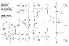
Before we move on, I want to share a modified version of this circuit that scraps the current dumping bridge in favor of an op-amp loading RC network that allows you to tweak the loop gain. The capacitor on the op-amp outputs creates a zero as did the CD bridge cap which allows for more feedback than without it. The result is a class-B amplifier that gives pretty good results.
Another interesting thing about this is the effect of different output configurations. So far it seems the original configuration is hard to beat.
Of course this design still doesn't have output protection (etc) so I would not call it complete.
Attachments
Last edited:
Before we move on, I want to share a modified version of this circuit that scraps the current dumping bridge in favor of an op-amp loading RC network that allows you to tweak the loop gain. The capacitor on the op-amp outputs creates a zero as did the CD bridge cap which allows for more feedback than without it. The result is a class-B amplifier that gives pretty good results.
Another interesting thing about this is the effect of different output configurations. So far it seems the original configuration is hard to beat.
Of course this design still doesn't have output protection (etc) so I would not call it complete.
I think you have to limit the ampop current when clipping.
In an old article in German's magazine "Funkschau" from the 80s was to find an other version of Quad's 405 approach with adjustable parts for "zero"-distortion (NE5534 as front-end).Steve, with all due respect, this is a design from last century and fully explained in several articles that can be downloaded for free.
In a sense the object IS to balance the feedback in the two situations: dumpers off, dumpers on. If the dumpers change state, so does the loop gain, and you normally get either xover distortion or gain doubling or a combination. By precisely adjusting the feedback to keep the loop gain the same in both situations, these distortions are, to a first effect, cancelled. The balanced bridge makes sure that the feedback ratios are precisely adjusted to counteract the changes in loop gain.
Jan
Who can upload this article ?
For me was always the most two interesting questions the follow:
1) the newer concepts like this uses in the class-A stage always a push-pull version. But the genuine concept of the 405 uses a single ended stage (Darlington Tr4/Tr7 and power resistors R30/R31 - this parts generate the highest temperature) - go to page 562 under
http://www.keith-snook.info/wireles...d-1975/Current Dumping Audio Amplifer DCD.pdf
According Nelson Pass a single ended stage for whole amplifier is the best solution - go to
https://www.passlabs.com/press/single-ended-class
Actually, that would have to be true in this situation, where the Class-A amplifier only takes over a part of it - isn't it ?
2) what happens, if the value of idle current for the class-A part is increased ? Maybe "ZERO" distortion is easier to reach ?
3) which OP-Amp as front-end provide the best acoustical results ? Maybe versions with only single voltage gain stage like the AD797 ?
Thank you for comments.
P.S.: an other approach for reducing distortion is this
Yamaha's Hyperbolic Conversion Amplification (HCA) Circuit
Last edited:
I think you have to limit the ampop current when clipping.
Ya, that's the purpose of R18 and R19 in the pass transistor collectors. But any over-current in the op-amp is going to over-bias the output in a fully complimentary VAS.
I have since managed similar results with the "RCA" version which avoids op-amp supply sensitivity, so I like that solution better.
I also note that the lack of emitter resistors for Q7 and Q8 (drivers) make the bias very touchy but necessary to achieve good THD. I think D Self had something to say about this phenomena?
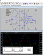
Simulating these amps is mysteriously sensitive to minor changes so I'm worried that I'm missing something bad going on.
And I have built amps without output protection, and rebuilt them too many times to do it again.
My bias against op-amp inputs has softened somewhat but only for larger amp that are necessarily complicated like this one.
Big amps are like muscle cars and trophy wives. I can't afford them. Well maybe I finally can now, but I choose not to.
2) what happens, if the value of idle current for the class-A part is increased ? Maybe "ZERO" distortion is easier to reach ?
Tried that. No zero THD.
3) which OP-Amp as front-end provide the best acoustical results ? Maybe versions with only single voltage gain stage like the AD797 ?
Simulated dozens. Lowest THD with OPA2132/OPA2134.
Regards.
You might try an CFP, replacing Q5,Q7 and Q6, Q8, to drive the MJs.
Already tried it. THD remains the same.
Any hints on how to improve the last schematic I posted?
I would like to maintain Q9/Q10 in Class-C.
Thanks.
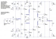
1. I'm worried about the thermal stability of bias from U2, especially without any emitter resistors on Q7,Q8. I understand you want Q9,Q10 in class C but I think you have to have Q7,Q8 running AB so the thermal tracking becomes critical.
2. You might add a speed-up cap across R15.
3.Why D5,D6?
4.The current in Q1,2,3,4 is a bit supply voltage sensitive. Do you plan to use a regulated supply? Is there a reason not to use the cascode between the op-amp and VAS? Op-amp circuits generally have to much gain causing stability problems so why Q1,2?
Playing with this I found that adding emitter resistors to the drivers offered thermal stability but ruined the THD. And I think CFP worked better than EF3??
Have fun.
1. I'm worried about the thermal stability of bias from U2, especially without any emitter resistors on Q7,Q8. I understand you want Q9,Q10 in class C but I think you have to have Q7,Q8 running AB so the thermal tracking becomes critical.
Tried emitter resistors. As you wrote, they ruined THD.
2. You might add a speed-up cap across R15.
Tried that. Lowest THD occurs without that capacitor.
3.Why D5,D6?
Better THD.
")
4.The current in Q1,2,3,4 is a bit supply voltage sensitive. Do you plan to use a regulated supply? Is there a reason not to use the cascode between the op-amp and VAS? Op-amp circuits generally have to much gain causing stability problems so why Q1,2?
Will not use a regulated supply.
I have tried a cascode there, but can't get much improvement. :-(
Playing with this I found that adding emitter resistors to the drivers offered thermal stability but ruined the THD. And I think CFP worked better than EF3??
Have fun.
I tried a CFP in Q7/Q8, but can't get it to run ok. Maybe I'm doing something wrong.
Thanks for your suggestions!
They are in class-C, no? Although I would put in just a single diode to lower the step at turn-on.
That is what QUAD did at the 2nd revision. Current dumping is a lot like feedback, it goes a long way but is not perfect.
Jan
Yes, a diode there will improve THD. But I also got cross conduction at saturation. Reduced R11 value to get rid of it.
Thanks.
My point about U2 is that it will not thermal track Q5,6,7,8. I would stick with a VBE multiplier.
In any case, you may want to post your model for the 431, or put it on the schematic. I found that most of them are bad. I forget the details but I think there was an if statement that made a bad assumption. There is also confusion between 2.5V and 1.25V parts with almost the same part number. And I think there is an LTC part that would avoid these problems in LTSpice.
In any case, you may want to post your model for the 431, or put it on the schematic. I found that most of them are bad. I forget the details but I think there was an if statement that made a bad assumption. There is also confusion between 2.5V and 1.25V parts with almost the same part number. And I think there is an LTC part that would avoid these problems in LTSpice.
suggestions
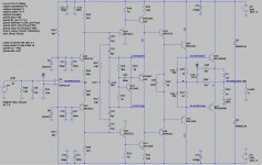
This is more like ~class-B but you can reduce R17 to ~4k3 to get back to class-C and still get good results. I think caps around the emitter resistors allows eating your THD cake and having thermal stability too.
But this circuit is marginally stable so I'm just doing this to be "helpful".
Have fun with it.
Attachments
- Home
- Amplifiers
- Solid State
- Current Dumping revisited