Hi all,
I got my hands on a used RA-01 at a great price. It's the European model that expects 230V input, and I'm in the States. From my background research, it seems like it should be possible to rewire this unit myself to run off US line voltage.
I checked the resistance between the neutral input to the main transformer and the other 3 posts at that connection (CON2 in the schematic). Post 1 is neutral, post 2 is a green input wire, post 3 is connected to orange and yellow input wires, and post 4 is a brown wire. (I believe I've interpreted the schematic correctly such that these numbers correspond to what's on there.) Resistance from 1 to 2 hovers around 1 ohm, from 1-3 is about 6.3, and 1-4 is about 13.3.
My schematic-reading skills aren't quite good enough to know what to do next, but from read the posts I linked to above, it seems like I probably need to move one of the wires from 3 to 4, and maybe also from 3 to 2? In the schematic I linked to, the input is specified at 115v and it shows two connections coming from posts 2 and 4 and none from 3. Maybe that's the correct configuration?
I'd really appreciate any advice or guidance any of you can offer! Thanks in advance!
Impossible to see the diagram, you have to download in your PC it and upload it again here.
Have you thought about avoiding headaches and not taking risks buying this ?...
Amazon.com: ELC T-1500 1500-Watt Voltage Converter Transformer - Step Up/Down - 110V/220V - Circuit Breaker Protection: Home Audio & Theater
Have you thought about avoiding headaches and not taking risks buying this ?...
Amazon.com: ELC T-1500 1500-Watt Voltage Converter Transformer - Step Up/Down - 110V/220V - Circuit Breaker Protection: Home Audio & Theater
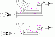
This Rotel RA 01 Service Manual shows the wiring for the 2 cases: AC 120V or 230V. At wiring diagram. ( Not schematic diagram )
It shows wire colors and wiring at CON2.
https://www.vintageshifi.com/repertoire-pdf/pdf/telecharge.php?pdf=Rotel-RA-01-Service-Manual.pdf
It shows wire colors and wiring at CON2.
https://www.vintageshifi.com/repertoire-pdf/pdf/telecharge.php?pdf=Rotel-RA-01-Service-Manual.pdf
Last edited:
This Rotel RA 01 Service Manual shows the wiring for the 2 cases: AC 120V or 230V. At wiring diagram. ( Not schematic diagram )
It shows wire colors and wiring at CON2.
https://www.vintageshifi.com/repertoire-pdf/pdf/telecharge.php?pdf=Rotel-RA-01-Service-Manual.pdf
There seems to be a discrepancy there. Both primary neutral wires go to terminal #2,
and the 120V line neutral goes to terminal #1. But there is NC between terminals #1 and #2.
My understanding:There seems to be a discrepancy there. Both primary neutral wires go to terminal #2,
and the 120V line neutral goes to terminal #1. But there is NC between terminals #1 and #2.
Mains plug go at CON1 in both cases, ( not drawn in the 120V case ).
Transformer has two 120V primary windings.
In the case: Mains 120V the two winding are parallel connected on CON2.
In the case: Mains 230V the two windings are serie connected on CON2.
Convertion is:
Rewiring at CON2 ( full respect of wire colors )
No change at CON1.
Appropriate AC cord for house mains socket.
Last edited:
...there is NC between terminals #1 and #2.
I read it as: The low end of the primary goes to pin 2, but the N Line connects to pin 1, which is a wire with a "square" on it, which I would suspect is the Thermal Cutout, and that runs to low end of the primary. This way the TP is working on either voltage.
As said above, the Schematic only shows 120V, the Wiring Diagram page 7 shows *both* versions.
Attachments
- Status
- This old topic is closed. If you want to reopen this topic, contact a moderator using the "Report Post" button.
