hi friends is there any one good on apex b500?
i have a little questions. first sorry abouth bad english.
i make this amplifier but never work stable. some times op amp burned some times 5200 or 1943 transistors but mostly mje340 and 350burning. i try contact with apex but i think he is bussy these days. i have many questions but try to make it simple.
1. first i want to ask is there really some one make this amp? i mean working long term stable? cause i make 6 of them and cannot make it work long time.
2. when it working it some times giving loud volume but some times its like a small pocket radio i cannot find it why.
3. when the amp not loud i take it out and start check it but accidently i put gnd cable to the input and it get spark and i cut electric but its late. after that it giving me -15vdc output. 5200 and 1943 are ok mje are ok i check all resistors are ok cannot find it what is the problem. when i close + and - fuses there is no problem it mean the problem at power stage but there is all ok.
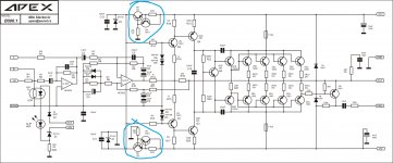
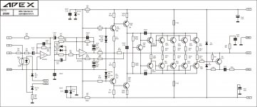
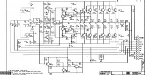
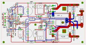
4. there is 2 schematic about b500 and b500.1 can any one tell me what doing that 2 transistor. i mean its for safe? or doing more power? i want to understand why he put thats in there. the pictures attached.
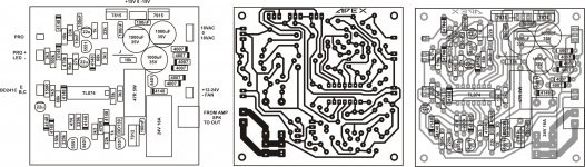
5. i use protection circuit too but there is some silly thing if i dont connect termal transistor it giving 2vdc at output (alone withouth amlifier) pictures attached.
power is 60-0-60 vdc.
pls i need help for understand why i getting problems and i want to make it work long therm use. thank you for help...
i have a little questions. first sorry abouth bad english.
i make this amplifier but never work stable. some times op amp burned some times 5200 or 1943 transistors but mostly mje340 and 350burning. i try contact with apex but i think he is bussy these days. i have many questions but try to make it simple.
1. first i want to ask is there really some one make this amp? i mean working long term stable? cause i make 6 of them and cannot make it work long time.
2. when it working it some times giving loud volume but some times its like a small pocket radio i cannot find it why.
3. when the amp not loud i take it out and start check it but accidently i put gnd cable to the input and it get spark and i cut electric but its late. after that it giving me -15vdc output. 5200 and 1943 are ok mje are ok i check all resistors are ok cannot find it what is the problem. when i close + and - fuses there is no problem it mean the problem at power stage but there is all ok.
4. there is 2 schematic about b500 and b500.1 can any one tell me what doing that 2 transistor. i mean its for safe? or doing more power? i want to understand why he put thats in there. the pictures attached.
5. i use protection circuit too but there is some silly thing if i dont connect termal transistor it giving 2vdc at output (alone withouth amlifier) pictures attached.
power is 60-0-60 vdc.
pls i need help for understand why i getting problems and i want to make it work long therm use. thank you for help...
Attachments
I build two. Work stable at maximum power. Even i used trash China transistors.
ty for write this is important for me did you get any problem when you build it? maybe that is not a problem for you but it ccan make me fix some thing.
ty for write this is important for me did you get any problem when you build it? maybe that is not a problem for you but it ccan make me fix some thing.
This will not help you but I recommended to
build Legend Quasor Dr. Bora Amp 1000W RMS @ 4 OHM +/- 95V DC
have strong and clear sound without problems
This will not help you but I recommended to
build Legend Quasor Dr. Bora Amp 1000W RMS @ 4 OHM +/- 95V DC
have strong and clear sound without problems
ty for advice but for now i have to find what is the problem on b500 i think i will make re buld it with %110 print. maybe next one i can built your advice. ty..
Did you check oscillation ?
normally driver need miller capacitor, B500 no have
add 500 PF between c and b and lokk problme is solved or not, this means transistor will not hot wenn problem solved
I have try to build may years ago APEX amp too but not work good
same with Apex Class D amplifier D200, some people try to build but not work or have problems
Did you check oscillation ?
normally driver need miller capacitor, B500 no have
add 500 PF between c and b and lokk problme is solved or not, this means transistor will not hot wenn problem solved
I have try to build may years ago APEX amp too but not work good
same with Apex Class D amplifier D200, some people try to build but not work or have problems
i dont have oscilloscope. i can try put caps at driver transistor collector to base it need to be 500pf right?
Last edited:
look BGW 750B schematic, circuit is similar and work good like a workhorse and sound very good
12 years I have enjoy the sound in nightclub
i dont see it yet my friend i will i promise and i think i will try it too.
 but now i have to fix this one. thank you
a new problem lol what happening friends its like a loki on me joking me all days.
when i open it, 15032 and 15033 too hot. others normal.
output have 0,4vdc. when i give input signal withouth signalgnd, there is stupid noise cominng like a bırrrrrrrrrr. but if i connect signal gnd it go. if i connect input signal gnd to starground then that noise coming again.
when i close power output getting dc voltage and going up some times to -20vdc. and its going down slowly to 0vdc.
any idea???
1 try to use working schematic BGW750B -
Important ! otherwise every amp will oscillate
look 1000PF Miller capacitor at transistors B and C Pin,
redesigned BGW750B PCB and FREE Gerber available soon
2. or Mosfet Legend Quasor, PCB and Gerber FREE available
1000W RMS if you extend and add 6 output deviecs
Important ! otherwise every amp will oscillate
look 1000PF Miller capacitor at transistors B and C Pin,
redesigned BGW750B PCB and FREE Gerber available soon
2. or Mosfet Legend Quasor, PCB and Gerber FREE available
1000W RMS if you extend and add 6 output deviecs
Attachments
1 try to use working schematic BGW750B -
Important ! otherwise every amp will oscillate
look 1000PF Miller capacitor at transistors B and C Pin,
redesigned BGW750B PCB and FREE Gerber available soon
2. or Mosfet Legend Quasor, PCB and Gerber FREE available
1000W RMS if you extend and add 6 output deviecs
do you have a clearer schematics or pdf doc of the amplifier, power supply, clip, signal and protection? i would like to make this amp.
do you have a clearer schematics or pdf doc of the amplifier, power supply, clip, signal and protection? i would like to make this amp.
Yes I have what do you like
1. BGW 750B Bipolar Transistor Amp, need 12 Bipolar Transistor per Channel
500W true RMS @ 4 Ohm within SOA +/- 80 V
or same Amp circuit
1800 Watt RMS @ 4 OHM + additional with Class TD Rail Switcher
need only 8 Bipolar Transistor per Channel
2. Mosfet Amp 1000W RMS ?
You can have 1000W RMS 4 OHM mit 1 pair Linear Mosfet
IXTK90N25L2
oder
IXTK110N20L2
960 Watt Mosfet power dissipation compare
Bipolars Transistor 150 Watt 2SC5200 / 2 SA1943
easy and cheap to build, strong and clear sound
look youtube
i can have both please thank you
Yes I have what do you like
1. BGW 750B Bipolar Transistor Amp, need 12 Bipolar Transistor per Channel
500W true RMS @ 4 Ohm within SOA +/- 80 V
or same Amp circuit
1800 Watt RMS @ 4 OHM + additional with Class TD Rail Switcher
need only 8 Bipolar Transistor per Channel
2. Mosfet Amp 1000W RMS ?
You can have 1000W RMS 4 OHM mit 1 pair Linear Mosfet
IXTK90N25L2
oder
IXTK110N20L2
960 Watt Mosfet power dissipation compare
Bipolars Transistor 150 Watt 2SC5200 / 2 SA1943
easy and cheap to build, strong and clear sound
look youtube
sir NMOS are you uploading the circuits you suggested, would like to have both
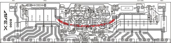
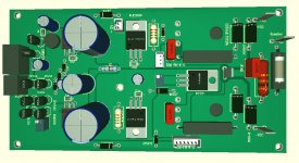
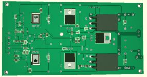
hi friends i make %110 bigger pcb. its working like all others. but when i checking again i find some thing and i want to ask is this normal.
on power pcb i have 4 big capasitors. one of them inside some thing moving when i hit little with finger. i dont know how to write it. its like a it dry and swinging inside. caouse of that i check the amp voltages. all is ok but when you close amp dc voltage going down slowly. its normal but positive side get 0 before then - and power start giving - voltage cause of that. should i change capasitor?
on power pcb i have 4 big capasitors. one of them inside some thing moving when i hit little with finger. i dont know how to write it. its like a it dry and swinging inside. caouse of that i check the amp voltages. all is ok but when you close amp dc voltage going down slowly. its normal but positive side get 0 before then - and power start giving - voltage cause of that. should i change capasitor?
1 try to use working schematic BGW750B -
Important ! otherwise every amp will oscillate
look 1000PF Miller capacitor at transistors B and C Pin,
redesigned BGW750B PCB and FREE Gerber available soon
2. or Mosfet Legend Quasor, PCB and Gerber FREE available
1000W RMS if you extend and add 6 output deviecs
i will try soon my friend ty.
hi all
can any one give me some mesurement for b500?
i have 0,47vdc on 5200 transistor base and 0,33vdc on 1943 transistor base. it can open transistor? this mesurement witouth signal.
i need some mesurement samples for b500
5200, 1943, 15033, 15032 and mje340 what they need on base and what is the bias voltage on the bias resistor its 330ohm i think. i think its 1v i was read before but i need to be sure cause too many pages i cannot find it again.
my power voltage is 60vdc.
thank you for answers...
- Status
- This old topic is closed. If you want to reopen this topic, contact a moderator using the "Report Post" button.
- Home
- Amplifiers
- Solid State
- APEX b500 questions