Hi everyone,
I'm restoring a venerable old NAD 3020 series 20 (silver one first serie). I got everything done (full recap, changing transistors on the regulator board witch where fried, installing new 2n3055/mj2955 pairs) I've setted the bias and offset without any trouble and finally put some music through the amp, perfectly fine for the first 3min or so, then BAMM!, magic smoke on the right channel......
Some precisions on the amp and what I've done:
The Amp is a first generation 3020
But some resistor values comes from 3020b amp:
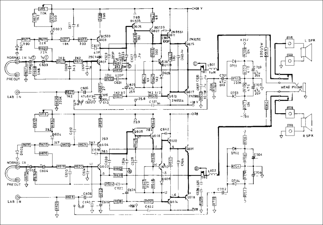
R647/648= 180r instead of 1k2
R635/636= 1k2 instead of 2k2
R627/628= 680r instead of 1k2
R629/630= 330r instead of 390r
There's no D605/606 on my amp (just a strap)
So after changing the caps, repairing the regulator board and controlling every semi on both channels I installed new pairs of 2n3055/mj2955 (they where absent).
I then installed 1R 3w resistors in place of the strap on r653/654 to measure and set bias, I also substitued RX1 and RX2 for 2K trimmer resistors.
The bias setting went smoothly and I was able to get 30mV on both sides (I controlled temperatures of all the fets and no one where higher than 36°). I let the amp warm for 15min or so to fine tune the bias. I also set the output offset to virtually 0 (0.2mV/0.4mV).
All of those manipulation where done with a light bulb tester in case something went fishy. After confirming the bias, I shorted both 1r resistors as per manual instruction.
So after all that I decided to take a listen to the amp. I plugged it directly to the mains and hooked a source to the aux input and started listening with headphone. No problem at all, sounds nice on both channels, at one time I pushed on the loudness button, tried tone pots, everythings fine.....then after 3 min or so, a little plop then no sound on the right channel, and smoke from the amp.
R652 as burnt, destroying c634 in the process, I tested the semi and Q610/612/614 and both the power trans Q616/618 where fried.
The left channel is intact.
Looks like some kind of oscillation destroyed the right channel, as the runaway started when signal was present.
What are your thoughts on this?
I'm restoring a venerable old NAD 3020 series 20 (silver one first serie). I got everything done (full recap, changing transistors on the regulator board witch where fried, installing new 2n3055/mj2955 pairs) I've setted the bias and offset without any trouble and finally put some music through the amp, perfectly fine for the first 3min or so, then BAMM!, magic smoke on the right channel......
Some precisions on the amp and what I've done:
The Amp is a first generation 3020
But some resistor values comes from 3020b amp:
R647/648= 180r instead of 1k2
R635/636= 1k2 instead of 2k2
R627/628= 680r instead of 1k2
R629/630= 330r instead of 390r
There's no D605/606 on my amp (just a strap)
So after changing the caps, repairing the regulator board and controlling every semi on both channels I installed new pairs of 2n3055/mj2955 (they where absent).
I then installed 1R 3w resistors in place of the strap on r653/654 to measure and set bias, I also substitued RX1 and RX2 for 2K trimmer resistors.
The bias setting went smoothly and I was able to get 30mV on both sides (I controlled temperatures of all the fets and no one where higher than 36°). I let the amp warm for 15min or so to fine tune the bias. I also set the output offset to virtually 0 (0.2mV/0.4mV).
All of those manipulation where done with a light bulb tester in case something went fishy. After confirming the bias, I shorted both 1r resistors as per manual instruction.
So after all that I decided to take a listen to the amp. I plugged it directly to the mains and hooked a source to the aux input and started listening with headphone. No problem at all, sounds nice on both channels, at one time I pushed on the loudness button, tried tone pots, everythings fine.....then after 3 min or so, a little plop then no sound on the right channel, and smoke from the amp.
R652 as burnt, destroying c634 in the process, I tested the semi and Q610/612/614 and both the power trans Q616/618 where fried.
The left channel is intact.
Looks like some kind of oscillation destroyed the right channel, as the runaway started when signal was present.
What are your thoughts on this?
If C634 is damaged, the amplifier is taking off because incorrect parts have been used. If the other semiconductors have been changed for substituted, that will cause the amplifier to take off and be very unstable.
Never use a resistor instead of the link, always close the solder bridge when 30mA is flowing normally.
Never use a resistor instead of the link, always close the solder bridge when 30mA is flowing normally.
Attachments
There is a sincere difference made in the bias circuits, but it does not explain why one channel is happy and the other not so.
R652 is blown by to much current... is that dc (bias) or ac (signal/oscillation) related?
Replace 2955/3055 with bc547/bc557 (cheap) with both Re of 1k to mimic the end stage.
If they blow, it won't hurt. But you're able to track down what the cause might be.
R652 is blown by to much current... is that dc (bias) or ac (signal/oscillation) related?
Replace 2955/3055 with bc547/bc557 (cheap) with both Re of 1k to mimic the end stage.
If they blow, it won't hurt. But you're able to track down what the cause might be.
Hi everyone,
All of those manipulation where done with a light bulb tester in case something went fishy. After confirming the bias, I shorted both 1r resistors as per manual instruction.
What are your thoughts on this?
Did you re-check the values after you remover the "light bulb tester"?
Just to follow up (I didn't have a chance to reply fully earlier).
It is common for 3020 series NADs to die shortly after being put back into service with replacement output transistors.
Apparently the NAD designs relied on the internal base-emitter resistance of the original hometaxial construction 2N2955/3055 for thermal stability, but the newer epitaxial parts do not have that resistance and therefore are not thermally stable enough for the design without compensation. That is why they require taming with emitter resistors.
There are plenty of threads with the information to carry out the mod (after the channel is repaired again). Search google for 'diyaudio.com nad 3020 emitter resistor' and you should find plenty of good info
Did you make any variations to the other components whilst restoring the amp?
With Q610 thermally coupled to the output heat sink, it will track the temperature changes. DO NOT fit the bodge emitter resistor, there is no advantage.
C634 is part of the output stage HF load network and only fails when the amplifier oscillates above 50kHZ, just before it destroys itself. Nothing to do with bias settings.
C634 is part of the output stage HF load network and only fails when the amplifier oscillates above 50kHZ, just before it destroys itself. Nothing to do with bias settings.
If C634 is damaged, the amplifier is taking off because incorrect parts have been used. If the other semiconductors have been changed for substituted, that will cause the amplifier to take off and be very unstable.
Never use a resistor instead of the link, always close the solder bridge when 30mA is flowing normally.
To be exact, C634 has been damaged by the burning res (they touch each other)
And of course I shorted both 1R resistor prior to inject signal
Can I change C634 with a Polyester 0.1uf instead of a mylar?
Last edited:
Just to follow up (I didn't have a chance to reply fully earlier).
It is common for 3020 series NADs to die shortly after being put back into service with replacement output transistors.
Apparently the NAD designs relied on the internal base-emitter resistance of the original hometaxial construction 2N2955/3055 for thermal stability, but the newer epitaxial parts do not have that resistance and therefore are not thermally stable enough for the design without compensation. That is why they require taming with emitter resistors.
There are plenty of threads with the information to carry out the mod (after the channel is repaired again). Search google for 'diyaudio.com nad 3020 emitter resistor' and you should find plenty of good info
Did you make any variations to the other components whilst restoring the amp?
So If I understand well I got to insert a resistor between the base of the power trans and the emitter of the driver (after R651/652 and C633/634).
Will a 4r7 res be ok as emitter res?
I'll also change Q611/612 to BD139/140 as the original one are not easily abtainable...
Nope. The amplifier is missing these guys, found on just about any other similar construction known to man:So If I understand well I got to insert a resistor between the base of the power trans and the emitter of the driver (after R651/652 and C633/634).
Typically 0.22 ohms 5 W.
The ones you mean also come in handy at times, but let's start with the basics.
Attachments
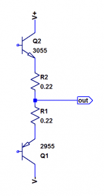
The 0.2-0.3 ohm emitter resistors will work to improve stability. But so will adding 10 ohm resistors from emitter of driver transistor to base of output. Sometimes called a “base stopper”, although the function here is thermal stability as opposed to the usual function of oscillation suppression. Modding it this way is reported to sound more like the original than doing it with emitter resistors.
Why? Because the original hometaxial transistors didn’t have a “built in emitter resistor”. They had high base-spreading resistance, which is in effect a base stopper. So using a high-ish value base stopper gives you the same mechanism of improving thermal stability as the original amplifier design.
Why? Because the original hometaxial transistors didn’t have a “built in emitter resistor”. They had high base-spreading resistance, which is in effect a base stopper. So using a high-ish value base stopper gives you the same mechanism of improving thermal stability as the original amplifier design.
As said above you need to add some resistance to the EMITTERS of the output transistors. 0.22-0.33 ohms will work. I find vitreous enamelled resistors rated for 3W work well for this.
Better to use MJE243/253 for the drivers - modern BD139/140 are not very good at it.
I got some 2sb649A and 2sd669A at hand, those may work well don't you think?
That was not made clear. Yes a Poly cap is fine.To be exact, C634 has been damaged by the burning res (they touch each other)
And of course I shorted both 1R resistor prior to inject signal
Can I change C634 with a Polyester 0.1uf instead of a mylar?
Being an ex NAD service centre, before I retired and have repaired many 3020s and it is always so much easier to be working on the amplifier than to second guess what may have happened.
I have never fitted emitter resistors as they do not require them if set up correctly. On-Semi 2N3055/MJ2955 are the same specification as the older Motorola semiconductors.
I got some 2sb649A and 2sd669A at hand, those may work well don't you think?
Certainly, if they are real ones. Many fakes would probably *work*, but depending on what you actually get they could exacerbate the thermal runaway problem if you’re not using emitter/base resistors. Putting in those makes the circuit more tolerant of transistor type, in general.
I got some 2sb649A and 2sd669A at hand, those may work well don't you think?
If they're the real deal, I think that's what NAD used in later versions of the circuit
Ok, so I rebuilt the entire right channel (with st 3055/2955, b649A/669A as drivers, a new bd139, new 180r metal resistor and 400v 0.1uf poly cap.)
I added base stopper resistors (10r 3w) on every output trans (left and right channels) .
I made bias adjustments with lightbulb, and everything went smoothly (has before), I got steady 30mV on both channels, every transistors between 26 and 30°c at the notable exception of Q506 on the preamp right channel witch where 10°c hotter than Q505 on the left one.
So, I tried adjusting bias on mains.... No problems, 30mV steady and I let the amp warming for more than 10mins.
So I decided to short the bias res (1R 3W) and listening to music..... I listened for 8 minutes without problems.
Confident that everything was fine now, in turned the amp on again to set the output offset (nothing connected on any inputs) and reached few mV on both sides just before........ Bam!!! Right channel smoked again..... 😭
Same thing as before, both drivers, bd139, 3055/2955, 180r res fried........ And left channel intact...... Something fishy here..... I checked the 4 remaining transistors on the right power section and they all seems fine (bc556A with an hfe of 141, bc559b hfe=309, bd139 hfe=65, 2sc1400 hfe=692 )...... I'm a bit lost here.
Now, I'm extremely motivated getting this amp fixed😉, I hope you'll have some advice/ideas to help me achieve this repair.
So I made a discover....
I rebuilt (one more time) the right Channel and this time spent an extensive amount of time monitoring things (on light bulb tester)
I set bias to 30mV on both sides and let the amp run for some times (with dmms still attached to bias points), in the meantime i checked temperature and still get hotter fets on right preamp channel.
Then after 10 or 15 mins, the bias on the right side collapsed all of a sudden (to 0. something), I immediatelly turned off the amp (even if the tester was not lited). then immediatly turn it back on.... the bias was still collapsed.
Turned off again but waiting some times before turning it back on (a minute or so). The bias was back again and rising normally to it's setted value of 30mV. After a few minutes, collapse again.
I then tried unlinking preamp from amp sections.
But the collapse still occured 10 minutes after turning it back on. So it seems that it's not the fault of the preamp stage.
What can cause this sort of bias collapsing?
- Status
- This old topic is closed. If you want to reopen this topic, contact a moderator using the "Report Post" button.
- Home
- Amplifiers
- Solid State
- Early NAD 3020 fried channel