On 1994,I have done a AMP use NE5534,this AMP sounds are very better, but biass of MOS is not stabilize, now I am doing the AMP,I plan to user a AVR CPU to monitor the biass of MOS and auto adjust biass of MOS.
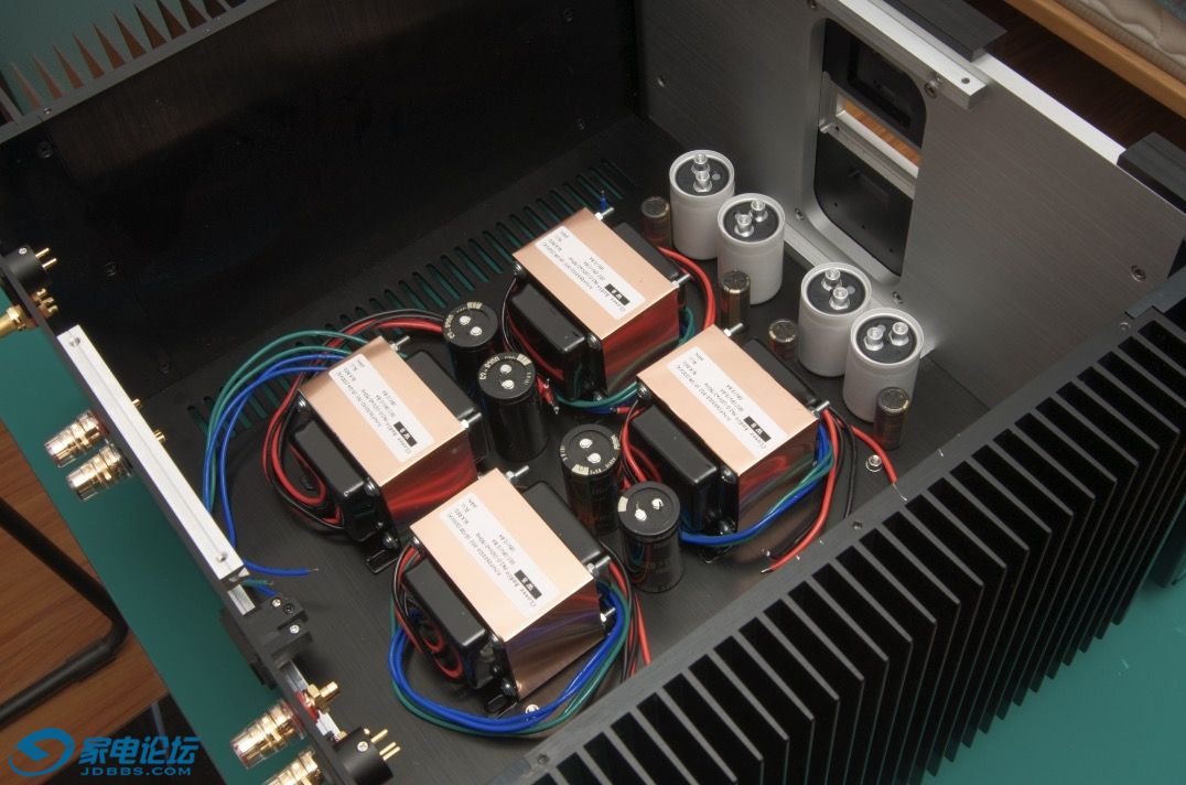
I use 4 power transformers:the NE5534,MOS each one use 1 transformer, and each channel use tow transformers
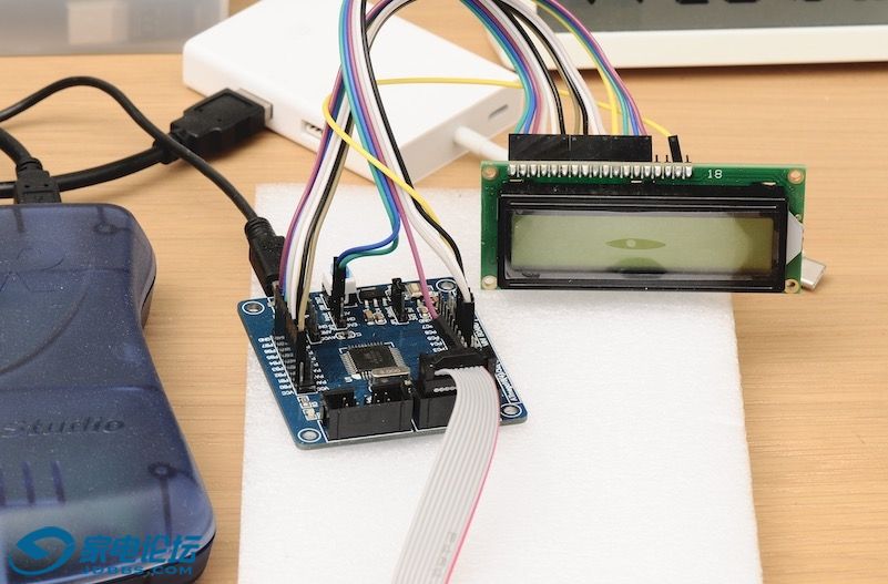
I begin to do AVR CPU Computer to monitor MOS biass
I use 4 power transformers:the NE5534,MOS each one use 1 transformer, and each channel use tow transformers
I begin to do AVR CPU Computer to monitor MOS biass
This is the same amplifier circuit we did in school lab in 1986 ...")
Do you monitor voltage across source resistors or temperature?where do you control the bias?
You know that a simple vgs multiplier on heatsink would control bias current by sensing temperature heatsink..
Fab
Do you monitor voltage across source resistors or temperature?where do you control the bias?
You know that a simple vgs multiplier on heatsink would control bias current by sensing temperature heatsink..
Fab
This is the same amplifier circuit we did in school lab in 1986 ...
Do you monitor voltage across source resistors or temperature?where do you control the bias?
You know that a simple vgs multiplier on heatsink would control bias current by sensing temperature heatsink..
Fab
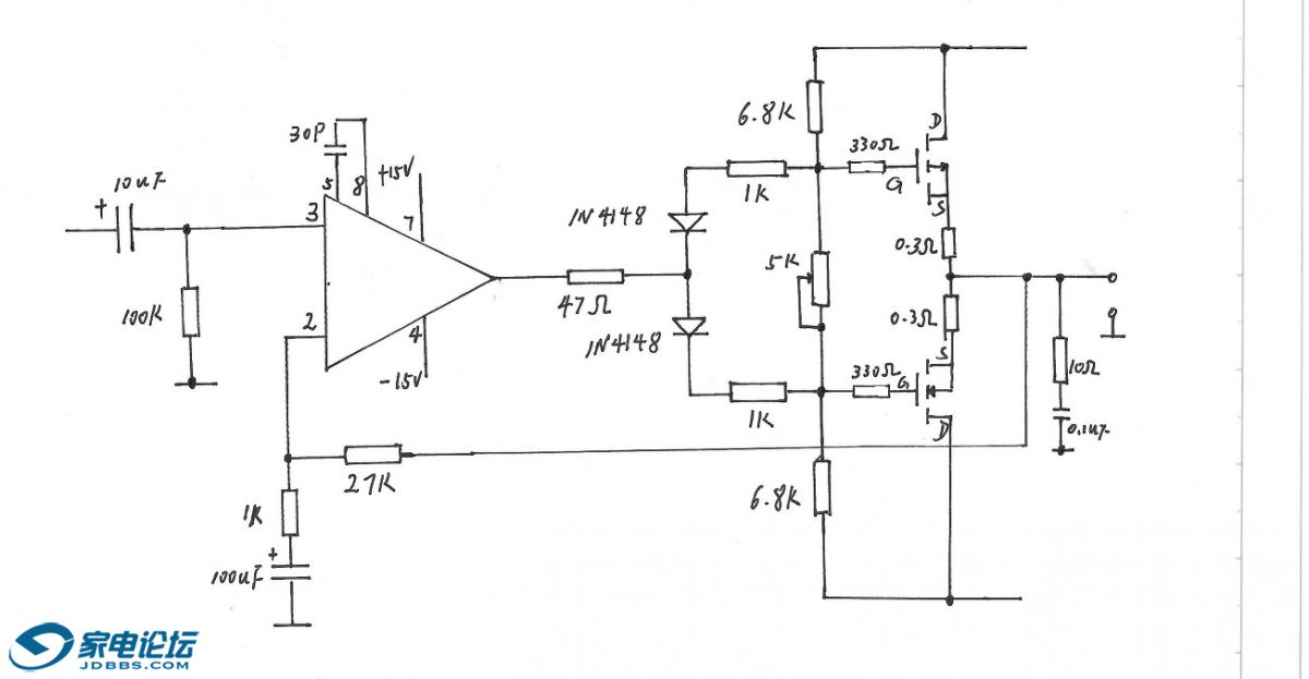
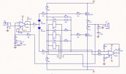
I use a OP-AMP IC to isolate MOS bias with CPU,CPU A/D the MOS bias then control 3 relay to switch bias resistance, please see and check my circuit if is exist bug
What is the max output of this amp? 20v pk-pk?
Jan
yes,I think pk-pk is 20V
Attachments
You should follow palstanturhin advice. This is how it was done by Denon in the 90’s for automatic bias and the main advantage that Denon claimed was that the circuit was set to reach more quickly the optimal bias after power up thus stabilized output transistors temperature. Based on your chassis and only about 20wrms in 4 ohms max I suppose that you will have a high bias in class A this takes a longer time to stabilize. Your solution with a cpu allows to change your target bias to start with a higher one after amp power up and then reduce it until temperature stabilization.
In your case you do not adjust against temperature and that is the flaw in your circuit since you monitor only the input voltage of the mosfet. Also, with 3 relays you only have a max of 8 voltage settings. With an opto you can adjust any required voltage level.
One additional note is that you should have a cap for frequency stability margin and from what I remembered we had installed it in the feedback loop....
Fab
Last edited:
Thank for your propose!I have not think about that adjust bias to reach stabilize quickly after power up, this time I will add the function in AMP.My AMP circuit output power is small,so if single AMP succeed,i will improve AMP to BTL circuit.I will add cap in feedback loop too.
Thanks!
Thanks!
I wonder if that compensation capacitor on the NE5534A is needed, given the gain of the circuit is greater than 3? Or perhaps it does need some compensation, but in the feedback path from the gate side of the MOSFETs? Kind of agreeing with fab's post...
The type of MOSFET is a mystery? Presumably not laterals (which would cure the problem)
The type of MOSFET is a mystery? Presumably not laterals (which would cure the problem)
- Status
- This old topic is closed. If you want to reopen this topic, contact a moderator using the "Report Post" button.
- Home
- Amplifiers
- Solid State
- Make an amp using NE5534