Hello people.
I decided to look at a Pioneer A-109 for a neighbour which won't power on, it's not something I'd like to own yet he likes it and with he being a vet, I'd love to help him out
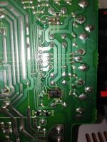
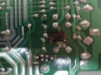
The problem is 4-6 resistors are burnt out in the speaker protection circuit under the board.
Would you replace the resistors with SMD?
I was thinking it's better to replace with normal fixed resistors as there's room.
Also how would you ground them? Clean the original ground points or re-route?
Here's some pics and photo of the printed schematic
I decided to look at a Pioneer A-109 for a neighbour which won't power on, it's not something I'd like to own yet he likes it and with he being a vet, I'd love to help him out
The problem is 4-6 resistors are burnt out in the speaker protection circuit under the board.
Would you replace the resistors with SMD?
I was thinking it's better to replace with normal fixed resistors as there's room.
Also how would you ground them? Clean the original ground points or re-route?
Here's some pics and photo of the printed schematic
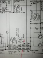
From the look of the circuit, this would appear to be the output Zobel network. The burnt resistors mean they have been passing a lot of current.
If you are lucky, the Zobel capacitors could be leaky, but it is much more likely that the output is oscillating. If this is the case, the new resistors will cook until you clear the fault causing the oscillation.
Alternatively, does the owner have the volume welded at 11? if so, you will never cure the cooking resistors, it is just the amplifier clipping and oscillating.
Kevin
Hi Kevin, thanks for the reply, very interesting.
All he said was the tone controls was not working, he got someone to look at it and now don't power on when it's returned.
I had no continuity on the small caps on the other side of the board 0.22uFs I was going to replace.
I feel the tone control problem was a still button as it's locked in place and will clean with Servisol or replace
Thanks again
Thanks for your input too jaycee, well appreciated
I was guessing the owner driven the low powered amp hard and/or with 4 ohms speakers which is not stated to handle.
All other components appear fine, maybe a dry SMD cap on the tone control board needs reflowing. I have a feeling this IC near the direct switch is faulty.
I have thousands of new cheap resistors but no 1.5 ohms haha. I'll order some through hole 1/4W or 1/2W. Replace the mylar 0.22uf caps I have spares of and hope that will just be it. Not worthy shotgunning more parts I feel.
Attachments
I wouldn't invest much time/expense at this stage...
Those burnt resistors look very bad news to me. Anything in the 3 to 10 ohm ballpark should be fine to keep an otherwise OK amp stable.
You say it doesn't power on which suggests something could have failed short circuit and taken out any fuses that might be in there. First check for me would be to see if the output transistors are short circuited.
Thanks Illi, Mooly and again Jaycee
It's definitely time I invested in a new multimeter as my 20 year old Fluke finally packed in last night, the screen is dead, could only get the beeps from continuity. I'll get a decent one ordered. The scope will have to wait haha
I'm thinking the output transistor test will need to test voltages not just continuity. Very likely they are gone.
How will I test the microprocessor chip?
4.7 ohm @ 1 watt seems easier and makes sense
Great help guys, I'm sure the vet down the road will be happy with you helping me out
If the outputs have failed then its 99.9% certain they will be reading almost short circuit from collector to emitter.
uP's are difficult (impossible) to verify on a one off basis although you can make an informed decision. Check the supplies are correct and check that the clock/oscillator is running and that any reset pins are released. Go around all pins on the chip with the scope looking for both DC voltages and any AC data that may be present and decide if it looks 'reasonable'. For example seeing 5 volts peak/peak of data on any relevant pins is a good sign, seeing perhaps a pin stuck at some indeterminate voltage with say a couple of 100mv of data riding on it might have you questioning and looking further.
Generally uP's are extremely reliable and 99% of issues lie elsewhere.
Also use a DBT (dim bulb tester) when powering the amp up, particularly if you have done any component replacements in the power amp sections.
Your a great help indeed,
I will step up and start investing in some good testing equipment as the hobby is not going away
I have lent him my Denon PMA250III for now and he loves it. Thinking he may not be as attached to this Pioneer now.
I can understand as he bought it new before going to Afghanistan and getting a head injury.
I will check output transistors later for continuity. I have a multimeter in the post
Thanks for your detailed reply as this will be good info for the future I'm sure
")
- Status
- This old topic is closed. If you want to reopen this topic, contact a moderator using the "Report Post" button.
- Home
- Amplifiers
- Solid State
- My first attempt at SMD repair. How would you do it?