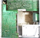
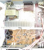
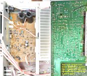
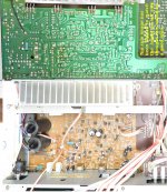
I recently found our old family receiver and put it in my room only to find out that the left channel was not working.
I opened it up to find that the left channel fuse was blown. I could not seem to find a match for that fuse type, but I found some PICO fuses in China that matched the 4A 125V.
After soldering it to the bottom joints of the fuse holder and regaining the connection, the channel still does not work, maybe something further upstream is damaged?
I have 0 experience with receivers or audio and could not find a schematic for the DRA-300. Just hoping someone might have a suggestion or schematic. I got a scope, meter etc
We really need to see a circuit to advise in detail, however basic checks would be...
1/ Check to make sure the replacement fuse is still intact (measure it) and that it has not silently blown.
2/ Try the unit with headphones while leaving the speakers disconnected.
3/ Try more than one input.
4/ If we assume the unit is DC coupled then you should check to see there is no DC offset present on the faulty channel speaker feed. Trace this feed all the way back to the PCB.
Imgur: The magic of the Internet
Imgur: The magic of the Internet
Imgur: The magic of the Internet
Imgur: The magic of the Internet
1) I checked with my multi metter (photod), it is showing that the fuse is good.
2. I do not have the 6.35mm jack or adapter, I can test to see if I get anything with my scope
3) I tried all the inputs and radio iirc, but will double check
4) Are the speaker feeds the mosfets responsible for controlling the power to the left and right channels?
Thanks Mooly
Imgur: The magic of the Internet
Imgur: The magic of the Internet
Imgur: The magic of the Internet
1) I checked with my multi metter (photod), it is showing that the fuse is good.
2. I do not have the 6.35mm jack or adapter, I can test to see if I get anything with my scope
3) I tried all the inputs and radio iirc, but will double check
4) Are the speaker feeds the mosfets responsible for controlling the power to the left and right channels?
Thanks Mooly
Last edited:
Are the output transistors FET's? What are the device numbers?
You could compare the DC voltages on those four transistors as measured from ground. Each pair should be similar. Be careful when measuring not to slip with the probe.
Any major difference would indicate a problem and typically we would be looking for a high DC voltage of either polarity on the pins that feed the speakers. Depending on the circuit configuration that could be either the Source or the Drain pins.
You should see supply voltage on whichever pins (Source or Drain) do not connect to the speaker output.
The most common configuration would have supply applied to the Drains, positive supply on the N channel FET Drain and negative on the P channel FET.
You can also scope the FET's and see if audio is present.
Are the output transistors FET's? What are the device numbers?
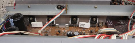
Here is a better pic: imgur.com/kjymNN5
Two of the transistors on the outside TR319 & T320: WingShing C2577
datasheet screenshot of C2577: imgur.com/l8Aq8H8
The other two in the middle, I am not sure. The company is WingShing also.
I will test them shortly and report back!
Try attaching your pictures directly ")
How to attach images to your posts.
C2577 are actually 2SC2577
2SC2577
And if all the outputs are the same type (no 2SA devices pairing them) then the output stage is a more unusual quasi complementary type.
How to attach images to your posts.
C2577 are actually 2SC2577
2SC2577
And if all the outputs are the same type (no 2SA devices pairing them) then the output stage is a more unusual quasi complementary type.
Roger that!Try attaching your pictures directly
I tested the 2SC2577 and the 2SA1102, they all seemed fine and were operating relatively within range of each other. There were no obvious signs that they were not working or there was a short
I tested the voltage on the headphone jack with the multimeter and they were both similar and the voltage was jumping around from .6 - 1.1 volts
side question: is the difference between the bipolar and fet transistors that one amplifies power while the other (fet) bucks the power?
In very simple terms bipolar transistors are 'current driven' and require a flow of current into (or out of depending whether NPN or PNP) the base in order to conduct.
FET's are voltage driven and at DC essentially draw no current into their 'Gate' from the stage driving them. At AC the driving stage has to supply enough current to charge and discharge the Gate capacitance.
Transistors have current gain. If 10 milliamps injected into the base causes a collector current of 500 milliamps to flow then the transistor has a basic current gain of 50.
The gain of a FET is expressed differently and this is called 'Transconductance' and that is a measure of the change of current flowing between Source and Drain of the device versus the change in voltage applied to the device (applied to the Gate).
We really need to see a circuit of the power amp to advise better what you should be seeing although the output of the amp should certainly be very close to zero volts at all times.
We really need to see a circuit of the power amp to advise better what you should be seeing although the output of the amp should certainly be very close to zero volts at all times.
I posted the images like you said but I had to down the quality 50% to post them here. This is a link to the original photos in one gallery JIC: Imgur: The magic of the Internet
I will record the measurements on the 4 output transistors and report back. I do not believe I was getting 0 volts on the emitter leg.
Attachments
Values are +- respectively. I tested voltage with a 1000 Hz w sine wave loop from youtube
2SC2577: B= 1.27v, C= 42.6v, E= 1.09v
2SA1102: B= 0.89v, C= 42.9v, E= 1.075v
I also noticed that the left hand resistor (R347), the silkscreen print is faded while the other is very clean and legible. I know it doesnt necessarily mean it is bad, but it could be. I have never seen a three leg resistor before except for a variable resistor. Never knew these existed, should I test them? If so, how?
Attachments
Last edited:
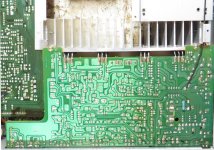
That last picture tells best how its configured.
The 2SC transistor should have the positive supply on the collector (your 42 volts) and the 2SA collector should have negative supply (so around -42v).
The white resistor is simple two 0.47 ohm resistors in series with the centre connection available. That centre connection is the main output of the amplifier. You can test those in circuit (amp off) and they should read 0.47 ohm from the middle leg to each end.
The DC voltage at the middle leg should be close to zero volts (no signal applied).
Both channels should give the same result.
Took results with another multi-meter when I notices my main meter wasn't registering the negative voltage on the A1102's.
Tested with a Fluke 15B+, with 1000Hz sound wave
w inputs connected but no sound
T319: B= 0.538v, C= 42.5v, E= 0.000v
T321: B= -0.537v, C= -43.1v, E= -0.002v
T322: B= -0.522v, C= -43.1v, E= -0.011v
T320: B= .555v, C= 42.57v, E= 0.017v
w/ sound playing:
T319: B= 0.2v, C= 42.5v, E= 0.545v
T321: B= -0.9v, C= -43.1v, E= -0.543v
T322: B= -0.8v, C= -42.5v, E= -0.422v
T320: B= .6v, C= 43.1v, E= 0.407v
The resistors were not registering at .47R from leg to leg. When off I am getting: 10 ohms leg to leg on R347 and 0 ohms leg to leg on R348.
Attachments

I recently found our old family receiver and put it in my room only to find out that the left channel was not working.
I opened it up to find that the left channel fuse was blown. I could not seem to find a match for that fuse type, but I found some PICO fuses in China that matched the 4A 125V.
After soldering it to the bottom joints of the fuse holder and regaining the connection, the channel still does not work, maybe something further upstream is damaged?
I have 0 experience with receivers or audio and could not find a schematic for the DRA-300. Just hoping someone might have a suggestion or schematic. I got a scope, meter etc
Your first mistake was not troublehooting the original problem, instead you've forced current back in again with a replacement fuse.
This likely does even more damage to parts that were not damaged originally.
That fuse has probably now blown, too.
With no experience in troubleshooting, perhaps letting an experienced tech take over, before it becomes a pretty paperweight or doorstop.
I hear you, but fuses bow from time to time, there is another post from 6 years ago for the DRA-300 left channel not working. It was apparently repaired when identified the burnt fuse and replaced it. That being said I will disconnect the fuse.Your first mistake was not troublehooting the original problem, instead you've forced current back in again with a replacement fuse.
Incorrect.That fuse has probably now blown, too.
I would like to gain experience with audio troubleshooting. Where did you start?With no experience in troubleshooting, perhaps letting an experienced tech take over, before it becomes a pretty paperweight or doorstop.
Thank you, any other tips would be appreciated!
I hear you, but fuses bow from time to time, there is another post from 6 years ago for the DRA-300 left channel not working. It was apparently repaired when identified the burnt fuse and replaced it. That being said I will disconnect the fuse.
Incorrect.
I would like to gain experience with audio troubleshooting. Where did you start?
Thank you, any other tips would be appreciated!
I started about 45 years ago in a classroom with a certified instructor, proceeded to get my degrees over time, (one pictured in my avatar) and ran several sucessful repair facilities through the decades, now recently retired.
Cool. Dunno what to say though, I am very familiar with electronic repair, just very new to amps. Some pointers would be appreciated, just trying to learn and hope someone is willing to help me, god knows Ive done it for others 1000 times. Any ideas on what I should test? I posted the results of the output transistors.
Last edited:
Took results with another multi-meter when I notices my main meter wasn't registering the negative voltage on the A1102's.
Tested with a Fluke 15B+, with 1000Hz sound wave
w inputs connected but no sound
T319: B= 0.538v, C= 42.5v, E= 0.000v
T321: B= -0.537v, C= -43.1v, E= -0.002v
T322: B= -0.522v, C= -43.1v, E= -0.011v
T320: B= .555v, C= 42.57v, E= 0.017v
w/ sound playing:
T319: B= 0.2v, C= 42.5v, E= 0.545v
T321: B= -0.9v, C= -43.1v, E= -0.543v
T322: B= -0.8v, C= -42.5v, E= -0.422v
T320: B= .6v, C= 43.1v, E= 0.407v
The resistors were not registering at .47R from leg to leg. When off I am getting: 10 ohms leg to leg on R347 and 0 ohms leg to leg on R348.
Those voltages look good.
The 0.47 ohm should be low enough in value to read accurately in circuit. First check the meter reads 0.00 ohm when the probes are shorted. Any additional value will be lead resistance and must be added to the final result, however even thin test leads should be in the 0.1 ohm range.
If you still read 10 ohm on R347 then you will have to investigate further by removing the part and retesting. Also try your meter on a selection of really low value resistors.

- Status
- This old topic is closed. If you want to reopen this topic, contact a moderator using the "Report Post" button.
- Home
- Amplifiers
- Solid State
- Denon DRA-300 Dead Left Channel