Servicing a Marantz 1070, I can't adjust the bias. Amplifier have audio output. I did the measurements following the service manual. The reading should be 10 mv, and I am reading only 0.5 mV at maximun rotation of the trimpot. The reading is the same in both channels. The offset adjustment is ok, the voltmeter indicates variation and I was able to set it in 0 mV.
I dont have any idea off what is causing this problem.
Any suggestions are wellcome.
I dont have any idea off what is causing this problem.
Any suggestions are wellcome.
The service manual shows a diode in each bias circuit, mounted on the heatsink - I'd check that has about 0.6V across it. The voltage difference between the bases of the driver transistors should be about 2.4V, ie +/-1.2V from the output voltage.
It sounds like something is reducing the voltage across the bias network (which is that diode and some resistors, thermistor and trimpot).
The drivers and output devices are factory? Perhaps they've been changed for different types? The outputs are 2SD388/2SB541, drivers 2SC1567/2SA794 (manual has a misprint, says 2SC388 for 2SD388)
Hi.Thank you for the sugestions.The service manual shows a diode in each bias circuit, mounted on the heatsink - I'd check that has about 0.6V across it. The voltage difference between the bases of the driver transistors should be about 2.4V, ie +/-1.2V from the output voltage.
It sounds like something is reducing the voltage across the bias network (which is that diode and some resistors, thermistor and trimpot).
The drivers and output devices are factory? Perhaps they've been changed for different types? The outputs are 2SD388/2SB541, drivers 2SC1567/2SA794 (manual has a misprint, says 2SC388 for 2SD388)
All transistors are original. The same as specified in the schematic and material list. I have done some measurments. The colector tension on the output transistors is a litle bit higher than the specs from the schematic, 38 volts.
The reading for the driver transitors measured, were below the indication. Increasing the bias trimer, they achieved almost the correct values.
Other issue, the emiter voltage on output transistor is reading in one side 38 mv and 60 mv on the other side. It shoul be 0 mv.
The diodes seems to be ok.
Thank you for de advise.Lots of mistakes in the Marantz SMs, make sure what the manual tells you is what you are actually measuring.
Craig
Hi. Following the indicated procedures in the SMS, I am only reading 0.5 mv. I took them off the PCB and measured them. They are working. The highest reading is 0.5 mv. Volume closed, no charge in the output. There must be something I am missing. As I said in the initial post, the amplifier is working. Output transistors are working cold.R711 and R712 don't work? They are for setting the DC offset.
Craig
one lead on chassi, and the other measuring on the transistors terminals. Am I doing it the wrong way?In post #4 you said you have 38mv and 60mv emitter voltage, how did you measure that?
Craig
Do you understand what llwhtt is saying? R711 and R712 do not adjust bias current. That is done with R733 and R734.
With your meter on DC volts and placed across the speaker terminals you should be able to adjust the offset voltage to zero with R711/712.
If the bias current will not adjust with R733 and R734 then you need to measure the voltage between the base of the two driver transistors and see how the voltage changes as you alter the presets. That will tell us if the control is at least working.
You measure the bias current by measuring the voltage across the 0.22 ohm emitter resistors and then calculate the current using ohms law. 50 milliamps would be a reading 11 millivolts for example. And remember, you measure across the resistor and not to it from ground.
And a word of caution") we see many problems appear on the forum of damage caused to amps through over enthusiastic tweaking and altering of settings. Be careful.
we see many problems appear on the forum of damage caused to amps through over enthusiastic tweaking and altering of settings. Be careful.
With your meter on DC volts and placed across the speaker terminals you should be able to adjust the offset voltage to zero with R711/712.
If the bias current will not adjust with R733 and R734 then you need to measure the voltage between the base of the two driver transistors and see how the voltage changes as you alter the presets. That will tell us if the control is at least working.
You measure the bias current by measuring the voltage across the 0.22 ohm emitter resistors and then calculate the current using ohms law. 50 milliamps would be a reading 11 millivolts for example. And remember, you measure across the resistor and not to it from ground.
And a word of caution
we see many problems appear on the forum of damage caused to amps through over enthusiastic tweaking and altering of settings. Be careful.Hi. I missunderstood DC adjust with bias when replying the post. I adjusted the dc out voltage, as I said in the first post. Its ok and I was able to set it near 0. The bias current is what I am not able to set. The max reading is 0.5 mv acrooss the emiter resistors, that I understand. The value that I read of 30 and 68 mv, I measured on terminal J716 and J 714, against groud. In the schematic, the value indicated is 0 v. I am not reading 30 or 68 mv across the 0,22 ohms resistors.Do you understand what llwhtt is saying? R711 and R712 do not adjust bias current. That is done with R733 and R734.
With your meter on DC volts and placed across the speaker terminals you should be able to adjust the offset voltage to zero with R711/712.
If the bias current will not adjust with R733 and R734 then you need to measure the voltage between the base of the two driver transistors and see how the voltage changes as you alter the presets. That will tell us if the control is at least working.
You measure the bias current by measuring the voltage across the 0.22 ohm emitter resistors and then calculate the current using ohms law. 50 milliamps would be a reading 11 millivolts for example. And remember, you measure across the resistor and not to it from ground.
And a word of caution
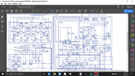
Yes, thats what I had done.OK now I think I see what you are doing. Put one DVM lead on J714 and the other lead on J716, NOW adjust the idle current. Same on J715 and J717. The only ground reference measurement is DC offset.
Craig
Its the same one that I have here.Is this legible:
- Status
- This old topic is closed. If you want to reopen this topic, contact a moderator using the "Report Post" button.
- Home
- Amplifiers
- Solid State
- Problem in adjusting bias in a Marantz 1070