Was just attempting to check a suspected bias immbalance on a working Speakercraft BB2125 2-chanel amplifier I have. I foolishly managed to short out one of the emiter resistors in the process. There was a bit of a pop and the fuse in the back panel blew (fuse in mains plug ok).
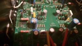
Meter probe must have connected one leg of an emitter resistor to a wire link on the PCB. The wire link disentigrated and now the shorted resistor reads 0.9ohms, not 0.4 like the rest. Red line in picture shows what I shorted and green line shows where the wire link ran.
Schematics for these amps are hard to come by and even with one I'd likely struggle.
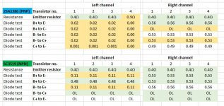
I tried testing the transistors (still on the board) using multi-meter in diode test mode. I'm very much a novice but recorded the results which look to me like all the left chanel transistors are damaged (all tests showed less than 0.02V); right side I think is ok although may not have recorded the results properly.
So, I guess I'm asking the wise folk here if there's any hope for this amplifier now? If I replaced the left chanel output devices might it be ok, or is the damage likely to be more extrensive.
Grateful for any help or recommendations on further diagnosis.
Meter probe must have connected one leg of an emitter resistor to a wire link on the PCB. The wire link disentigrated and now the shorted resistor reads 0.9ohms, not 0.4 like the rest. Red line in picture shows what I shorted and green line shows where the wire link ran.
Schematics for these amps are hard to come by and even with one I'd likely struggle.
I tried testing the transistors (still on the board) using multi-meter in diode test mode. I'm very much a novice but recorded the results which look to me like all the left chanel transistors are damaged (all tests showed less than 0.02V); right side I think is ok although may not have recorded the results properly.
So, I guess I'm asking the wise folk here if there's any hope for this amplifier now? If I replaced the left chanel output devices might it be ok, or is the damage likely to be more extrensive.
Grateful for any help or recommendations on further diagnosis.
Attachments
Anything can be fixed, it depends how much time and money you want to put into it. Normally you replace one stage before the damaged parts. If your outputs are blown and the drivers are fine, replace the outputs and drivers. If the drivers are damaged replace the pre-drivers or VAS transistors, depending on the circuit.
Normally you replace one stage before the damaged parts. If your outputs are blown and the drivers are fine, replace the outputs and drivers. If the drivers are damaged replace the pre-drivers or VAS transistors, depending on the circuit.
Why, if they're good? I'm not sure I follow the logic here.
Why, if they're good? I'm not sure I follow the logic here.
He's going by the usual proper toubleshooting techniques, as us techs have done from experience.
Is it because they are likely to have been stressed and may fail soon anyway?He's going by the usual proper toubleshooting techniques, as us techs have done from experience.
Roger that. Plus taking the case off & on again is $s more than some 80 cent drivers or op amps. Bad drivers can damage your $4 apiece output transistors again.
To be explicit bud barnet, yes you wrecked the amp. Those left channel output transistors are garbage.
Buy output transistors in sets, from the same vendor on the same day, and for best match buy in quantities of 25 (a whole tube). If you can't afford that many, buy 2 or 3 more than you need, measure Vbe and don't use the ones that are not the same value as most of them.
Last edited:
You need to remove and test the transistors. Remember that they are effectively in parallel and so if just one failed it would affect the readings seen across the others.
Such paralleled devices usually mean that they should all be replaced as a set of matched devices, or at least be from the same batch.
The advice to replace the drivers is absolutely sound and should be followed.
The bias should be turned to minimum before powering the amp up and a current limited supply (bulb tester) used at all times whilst working on this.
Why, if they're good? I'm not sure I follow the logic here.
When parts fail there is usually high current and voltage produced. In the case of arcing like this extremely high voltages are produced. Whatever is driving the damaged parts would have taken a hard hit and are likely damaged even if it's not evident.
The initial measurements indicate shorted output devices. This generally takes out the drivers also.
The advice to replace everything after the VAS is not bad advice, though i have to admit that if I were trying to save a buck I'd just do the output devices and drivers.
In most cases you might be saving literally a buck. Is it worth tearing down a second time to save $1? I value my time a lot more than that!
I recommend the use of insulated hook-probes when connecting to live circuits, much less chance of shorting anything out. Such as 10pcs multimeter lead wire probe test hook kit connector electronics laborator Sale - Banggood.com
Yes! Or at the very least, sheath your probe. Protection is crucial, to avoid expensive consequences [emoji31]I recommend the use of insulated hook-probes when connecting to live circuits, much less chance of shorting anything out. Such as 10pcs multimeter lead wire probe test hook kit connector electronics laborator Sale - Banggood.com
I recommend the use of insulated hook-probes when connecting to live circuits, much less chance of shorting anything out. Such as 10pcs multimeter lead wire probe test hook kit connector electronics laborator Sale - Banggood.com
I don't know about "bang good"'s products, but they're obviously asian based, and my experience with buying from those places often result in cheaply made stuff.
And I don't like cheap tools, particularly with my good Fluke meters.
I want accurate readings, period.
A good, versatile military grade set of probes is available and on sale from Apex Jr's site.
http://www.apexjr.com/images/TESTLEADSET.jpg
Ok, some good advice coming through - thanks guys.
Consensus clearly to replace at least the outputs and drivers.
Prices for the output transistors seem to vary significantly. Don't want to shell out too much especially if I don't manage to repair the amp properly and end up destroying them again.
There are some good value sets on eBay but some don’t look original, and others have some dubious feedback for fake transistors.
5pair(10pcs) 2SA1386 & 2SC3519 SANKEN Transistor A1386 & C3519 | eBay
Consensus clearly to replace at least the outputs and drivers.
Buy output transistors in sets, from the same vendor on the same day, and for best match buy in quantities of 25 (a whole tube). If you can't afford that many, buy 2 or 3 more than you need, measure Vbe and don't use the ones that are not the same value as most of them.
Prices for the output transistors seem to vary significantly. Don't want to shell out too much especially if I don't manage to repair the amp properly and end up destroying them again.
There are some good value sets on eBay but some don’t look original, and others have some dubious feedback for fake transistors.
5pair(10pcs) 2SA1386 & 2SC3519 SANKEN Transistor A1386 & C3519 | eBay
Yes, something like these would almost certainly prevented my mishap. Will take precautions next time.I recommend the use of insulated hook-probes when connecting to live circuits, much less chance of shorting anything out.
Thanks for this and the links provided by others.
I’ve got a replacement slow fuse on the way and been checking how to make and use a bulb tester as advised by Mooly here.
Don't ever buy transistors on ebay except from known posters on here or hifiengine. See "my transistors real or fake" sticky thread at the top of parts forum.There are some good value sets on eBay but some don’t look original, and others have some dubious feedback for fake transistors.
5pair(10pcs) 2SA1386 & 2SC3519 SANKEN Transistor A1386 & C3519 | eBay
I buy from farnell (newark in us) or digikey. in UK RS has a following. (Not Radio Shack) Authorized distributors of the real manufacturers. And some "manufacturers" leave all the specifications off their datasheets, like NTE, central semi, others. Even fairchild leaves some important hard to control specs off. There are no sanken or toshiba distributors in the US that I know of. (there is allegro?) Some german distributor has things I can't get here but I don't remember the name, freight is too high across the Atlantic for me to consider them.
Matching numbers is not important imho. Match package size, exceed the rail voltage by 2x with the Vceo, make sure the DC soa spec at your rail voltage exceeds [sqrt (ampwattage/(rating impedance)]/(number of parallel output transistors). For 1960s-70s amps there is a Ft consideration, but not with amps built after TO247 and TO263 packages were sold.
Last edited:
Ok, some good advice coming through - thanks guys.
Consensus clearly to replace at least the outputs and drivers.
And verify every resistor in the chain in case any have changed value or opened up due to stress.
Not just a visual inspection - use the DVM.
[/QUOTE][/QUOTE]
The emitter resistor that I shorted appears to have changed value, will check all nearby unless there are particular ones to focus on. The bands indicate they shoud be 0.33ohm 5% but unsure on type or power rating. They measure 5mm diameter and 15mm length - maybe 3W carbon film?
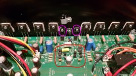
I'm actually not sure which the different ampifier sections are on the board. I've attached a picutre. I think the purple highlighted are the drivers, and the red section VAS? The purple highlighted transistors look to 2SD1763A & 2SB1186A and are connected to the drivers.
Is anyone confirm just from looking?
Thanks again.
And verify every resistor in the chain in case any have changed value or opened up due to stress.
Not just a visual inspection - use the DVM.
The emitter resistor that I shorted appears to have changed value, will check all nearby unless there are particular ones to focus on. The bands indicate they shoud be 0.33ohm 5% but unsure on type or power rating. They measure 5mm diameter and 15mm length - maybe 3W carbon film?
I'm actually not sure which the different ampifier sections are on the board. I've attached a picutre. I think the purple highlighted are the drivers, and the red section VAS? The purple highlighted transistors look to 2SD1763A & 2SB1186A and are connected to the drivers.
Is anyone confirm just from looking?
Thanks again.
Attachments
Last edited:
The purple ones are likely drivers. With the ohmmeter check that the emitter of the driver goes to the base (left pin) of the output transistors. I don't know which pin of the purple ones is the emitter, you'll have to download the datasheet from datasheetcatalog.com yourself. (I don't want it, I can't buy real 2sa 2sb 2sd parts). The 2 is usually omitted from the part label.
The one in the middle of the purple ones is the temperature sensor, likely also blown. Also whatever connects to the bare wire you shorted your probe too is also very suspect.
Likely your emitter resistors are 3W. If you can fit in 5 W for replacements, do it.
Don't neglect to put a limiter resistor in your AC line before hot testing. 100 W tungsten bulbs used to work but those are illegal now here except in charity resale shops. About 6 ohms to 8 ohms 100 watt resistor. People in the UK report single cup tea boilers work. (Put in the water, they burn up otherwise if you have a problem). We can't buy those here either. If the light bulb lights up (tea boiler doesn't) you have a problem. DC on speaker out >0.1 v is a very bad sign. I put light bulb in grounded box with cord feed, switch, circuit breaker 15 A, and an outlet. No wires to come unscrewed from bulb base and fly around sparking everywhere.
Don't connect good speakers at first, use used ones from dead TV's on the curb or car junkyards or something. charity resale shop here sells used drivers; just found a projection TV on curb last month, popped front off and salvaged 6" speakers in about 10 minutes off my bicycle.
Last edited:
Ok, yes that checks out. Get about 10ohms restance between but it's the same on the right channel.With the ohmmeter check that the emitter of the driver goes to the base (left pin) of the output transistors.
Damn, thought that would probably be ok but didn't check.The one in the middle of the purple ones is the temperature sensor, likely also blown.
Double damn. Would be best to remove the PCB first to access it, but when it first happened I tried probing a few parts that connect ot the wire that gut burned and seemed plenty is connectedAlso whatever connects to the bare wire you shorted your probe too is also very suspect.

I haven't removed the PCB yet to check full extent.
Will heed all advice regarding first turn-on/testing with a bulb in series. I'm sure I have some old lamps that I can adapt.
Might have an old drive unit to test with, but been having a clear out recently so may need to rummage in the charity shops otherwise and keep a beady eye out for skip contents too. I do have an old oscilloscope if that would help.
- Status
- This old topic is closed. If you want to reopen this topic, contact a moderator using the "Report Post" button.
- Home
- Amplifiers
- Solid State
- Did I wreck the amp?