Hello,
I always wanted to restore a solid state amplifier after playing with tube equipment. I wanted it to be something special, exciting, unique and decided on a V-Fet Sony and ended up with this TAN-8550, despite all the warning signs around it.
So, as soon as it arrived, I checked the famous diodes, and they were bad. That result didn't give me any hope for the V-Fets, and sure enough, 4 out of the 12 were shorted. (Interesting enough, only the 2SJ18s seems to be shorted (2 from each channel) and the rest has the same Vgs value as they are factory matched, I think.)
Diving into the dust and the dirt of the online auction sites and using search phrases like "assorted to-3 lot", "nos transistor lot", "Sony transistor to-3" and alike, I could be able to score a couple 2SJ18s with different ratings (all being 53 and above, 53 being the lowest mentioned transistor in the service manual). After my luck run out, I have reached some people from here for more spares and ordered a few 2SJ18s from different sources.
Now, my question is, after hopefully having more than 4 what supposed to be 2SJ18s, how can I match hem among themselves and with the ones that were already installed in the amplifier. I have this simple curve tracer from PEAK the DCA75 but the voltage settings are beyond me. I am a "push the green button, wait for the OK sign" kind of a guy when it comes to solid state. In the manual, it mentions about which resistors to change to which value if unmatched transistors are to be used, but I want to get as close as possible.
It would be great if this thread turns out to be a "screen capture" of today, the challenges, difficulties and problems that some one could face if they chose to restore a TAN-8550 and also a how-to / not-to guide, as I haven't seen any complete thread about the restoration of this amplifier. And some threads date back to 2002...2005.
Best Wishes,
Dirk
does the amp use source ( emitter ) resistors 0.22 ohm range?
use a 100watt incadescent bulb in series with the power plug. you can hack a cheap power bar for this.
Doing so will save your new parts an unwanted instant death if something is still wrong.
Thanks! Everybody warns against using a variac for powering this up or suggest turning up the variac to the full voltage under 5 seconds, but this method looks much simpler to execute. I can follow the reasoning behind the suggestions, besides the service manual mentions disconnecting the brown and violet cables (in my amplifier I don't have a violet colored cable, instead it is orange) basically disconnecting the Class B board from the large capacitor. I hope I come to state to be able to execute this soon.
Schematic?
I was lucky enough to score the original service manual at the local Ham Radio Swap Meet, alongside with all the other TA-N series preamplifiers and amplifiers. However, as usual, the schematic is available for free from HiFiEngine:
Sony TAN-8550 - Manual - Stereo Power Amplifier - HiFi Engine
if the amp powers up by placing a large pulse of cross conduction on startup while the dc capacitors charge and regulators stabilize, it's a design sure to fail.
The bulb will prevent damage to the amp by limiting the power. If the bulb stays on fairly bright then shut off the amp.
if it is a class A amplifier, the bulb will light fairly bright as a function of the (normally high) idle current. The amp should still operate at lower power levels. Currents and voltages should be measured.
those varactor "death diodes" should be replaced by 2 x 1N4148 diodes in series
if you have a schematic, it would be helpful as quick web search revealed 1 site saying the unit actually may die if a variac or bulb is used.
Last edited:
and why not disassemble the amp, sell in spare parts at a golden price, and buy another wonder (this is not what is missing)
who can be reparable in the next 20 or 30 years?
I know, my intervention is not very constructive, but with time, I became allergic to the amp that made sweat at power on...
who can be reparable in the next 20 or 30 years?
I know, my intervention is not very constructive, but with time, I became allergic to the amp that made sweat at power on...
advice : put amp on shelf , decide what amount of time to invest in reading everything you can find about service of these , start reading and soak in .....
only then proceed , when you feel prepared
done full service on few of these and will do it again strictly for adequate money ; wasn't impressed with sound at all ; they're what they are - milestone or something as that , but as I'm older - I learned to respect (and learn from) milestones and stop using them , when better things are around
Thanks! Everybody warns against using a variac for powering this up or suggest turning up the variac to the full voltage under 5 seconds, but this method looks much simpler to execute. I can follow the reasoning behind the suggestions, besides the service manual mentions disconnecting the brown and violet cables (in my amplifier I don't have a violet colored cable, instead it is orange) basically disconnecting the Class B board from the large capacitor. I hope I come to state to be able to execute this soon.
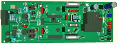
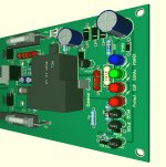
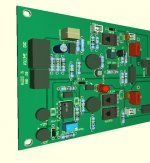
Why do you not replace old Internal Sony Mosfet PCB
with todays reliable High End Mosfet Technology all in one PCB ?
200 x 78 mm DC Protect, ....
Only rewire and add to heatsinks. work from 30 to 90V
Also the heat is much lower comoare old Sony V-Fet Design
Attachments
Why do you not replace old Internal Sony Mosfet PCB
with todays reliable High End Mosfet Technology all in one PCB ?
One reason may be the "old Internal Sony Mosfet PCB" is actually not mosfet
")
this gear has a high resale price that mat be ruined by putting in better parts. I used a $200 sx-780 and $90 SX3700 for this purpose. It smokes the old version completely but is not stock at all.
Tube preamp, mos amp , tuner improvements, subwoofer drive , new phono stage, iphone balancing. 50k gear may be able to keep up with it now but the resale value is minimal.
Keep it stock if you want to keep resale value.
Tube preamp, mos amp , tuner improvements, subwoofer drive , new phono stage, iphone balancing. 50k gear may be able to keep up with it now but the resale value is minimal.
Keep it stock if you want to keep resale value.
You could start by removing output transistors.
Feed back output of VAS stage to ltp.
This will give an amp that wont blow up output stage.
You can then check voltages at your leisure.
Make sure dc offset and bias voltage look right.
This response is a little bit cryptic for me. I need to understand what VAS (definitely not the equivalent air volume of the Kms of a loudspeaker) and Itp are.
This amp has a >$1500 ebay value so replace all possibly defective parts keeping it as close to stock as possible. It's a really expensive case for a modified amp.
start with the 3? varactor diodes with 2 IN4148's and the dead outputs
Thank you for naming the diodes. I have seen that these are being replaced but I couldn’t e sure about the correct part numbers. My next question was exactly this.
For me, it is the appreciation of the community that makes a specific product to stand out, as compared to other products, at a certain time period. I do not think it is related with how it is marketed or how it is priced or the marketing stories around it. When restoring an equipment, my pursuit is it to recreate that magical moment that pulled the attention to this equipment, therefore staying as loyal as possible to the original design and components. I don’t really care about other peoples voicing preferences by adding or removing non-period modifications. Besides, I always regretted the equipment that I had to leave behind because of the moves between countries for work, lack of space, etc. Now, I am keeping everything and enjoying swapping them in and out of my system.
VFET are great sounding amps, but discontinued from Sony and Yamaha late 70s
Poor rubbish circuit design:
1. Sony used an varactor dual-diode package in the bias circuitry of these amps, often they fail and kill the VFETs -
Sony Vfet = self destructing amp
2. Audio circuit is not reliable, engineering faults, a lot of service bulletin updates
3. To much heat for small power decrease lifetime for VFET devices
VFETs have an internal resistance 4 times greater than Bipolar Transistors or 7 times greater than switching mosfets.
This means a lot of heat compare to BJT devices already in standby,
4. Mosfet amp with IRFP / IXYS switching mosfets are cold at same Voltage/Output power
same great sound experience without any problems like old poor 70s Sony design
This advantages can be summarised as follows:
The internal resistance is 7 x lower for the switching mosfets compare VFets or 4 x lower compare to the bipolar transistors, meaning that the amplifier will operate very much colder and with strong and well controlled bass
The fast operation of the VFETs ode todays Switching mosfets gives both a treble transparency only achieved by the valve amplifiers and a very low TIM (Transient Intermodulation Distortion).
To much Sony VFET amps not working reliable and blow up, there was no future for VFETS and Sony stop late 70s production.
Same with lateral Audio Mosfets in Professional PA amplifier.
Many years ago Amplifier manufacturer stop Production with audio Mosfets about similar problems like VFETS
Lateral Mosfet Amplifier have much more heat compare to BJT.
With Switching mosfets you can build very rugged reliable Class AB amplifier
- Home
- Amplifiers
- Solid State
- Got a Sony TAN-8550 with fried 2SJ18s, now what?