I want to make some mods to this A700 amp .
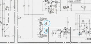
Regarding the 2 x 1000uf caps posted in the photo .
Those should be the 16v filtering rails for the pre right ?.
I was thinking to increase the UF to 2000uf for that location .
This will be safe for all components ?.
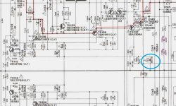
Also what about the 680uf 80V ones from the other photo .
It is safe to increase those to 1000uf ?
Thanks
Regarding the 2 x 1000uf caps posted in the photo .
Those should be the 16v filtering rails for the pre right ?.
I was thinking to increase the UF to 2000uf for that location .
This will be safe for all components ?.
Also what about the 680uf 80V ones from the other photo .
It is safe to increase those to 1000uf ?
Thanks
Attachments
I agree, do not arbitrarily change values, it might make no difference at all and as said above could risk damage.
Once you change one ecap, then logically they all should be changed if the thinking is that they are out of spec, so need changing.
If you know of specific parts that fail prematurely then by all rights change out the weak links.
Once you change one ecap, then logically they all should be changed if the thinking is that they are out of spec, so need changing.
If you know of specific parts that fail prematurely then by all rights change out the weak links.
The A-700 is about 35 years old, caps may still be ok.
I'm guessing that it sounds ok but not great hence your
posting about possible improvements.
I'd certainly run through a basic health check, see
"General Adjustments" chapter.
I would probably make the same cap changes as posted and
replace/increase the main filter caps. As pointed out, I
wouldn't expect any significant improvement in SQ from the
regulated supply.
I think you would have greater SQ improvement by replacing
any audio path polyester caps with FKP/MKP types, space
permitting. Also consider replacing audio path electrolytic's
with polyester.
Candidates would be
C125 (MKS?)
C133 (MKS or Nichi ES)
C156 (MKP?)
Recapping the power supply is not a bad idea, the ripple in class A
can take its toll.
The A-700 is about 35 years old, caps may still be ok.
I'm guessing that it sounds ok but not great hence your
posting about possible improvements.
I'd certainly run through a basic health check, see
"General Adjustments" chapter.
I would probably make the same cap changes as posted and
replace/increase the main filter caps. As pointed out, I
wouldn't expect any significant improvement in SQ from the
regulated supply.
I think you would have greater SQ improvement by replacing
any audio path polyester caps with FKP/MKP types, space
permitting. Also consider replacing audio path electrolytic's
with polyester.
Candidates would be
C125 (MKS?)
C133 (MKS or Nichi ES)
C156 (MKP?)
Recapping the power supply is not a bad idea, the ripple in class A
can take its toll.
I watched the service manual and this amp is full of mylar caps and some films besides electrolytics .
I don't see any cap marked as being polyester in this manual .
Those mylar caps are worth to be replaced ?.
I'd say your better off changing mylar caps to good Wima polys rather than increasing capacitance. E-caps in the signal paths valued 3.3uF or under to polys, even better improvement. As stated, space permitted.
If increasing capacitance really plays on your mind try the big filter caps to next popular value later.
If increasing capacitance really plays on your mind try the big filter caps to next popular value later.
Mylar=polyester, mylar is the trade name of some US(?) company.
I would not unconditionally replace mylar caps. Only consider caps that are in the audio path. Certainly mylar will be used in the loudness/filtering and tone areas. I don't use loudness and bypass the tone (ie, direct mode) where possible.
When replacing caps you should work out the basic function of the cap, eg, local storage, coupling, audio low noise,audio,, and then replace with a modern day equivalent. Seen too many people replacing caps in the (VU) meter circuit with more expensive (than necessary) options.
Certainly use polyproplyene over electrolytics and polyester if they fit. I think the pecking order is FKP then MKP then MKS, happy to be corrected.
This model appears to be one of those affected by the Fixing Glue of Death. This stuff, originally used to hold in components during assembly, has a tendency to go brown and even black while becoming brittle, acidic and corrosive, eating away at everything metallic it covers. Suffice it to say that the stuff needs to be removed thoroughly, and any damaged wire links or components replaced.
Upsizing C211P/212P seems uncritical. It only affects resistor dropper loading on powerup, and since that is not a great deal different from idle to begin with, I don't see any major issues. I would note down their diameter and then look up what the highest capacity is that you can get in a 35 V rating from a good-quality, lowish ESR cap series (e.g. Panasonic FC). If that happens to be a 2200 µF, go with it.
C210 is a 680µ/80V part... it's not trivial to find a replacement for that, let alone an upgrade. From the Panasonic stable, I would probably use the FC 680µF/100V part, as while they have some other series with 1000µ/100V parts, their ESR appears to be a factor of 2 or 3 higher if you do the math. They're making an FS series 680µ/80V with even lower ESR, but that seems a bit tight.
I would always go up in voltage rating with modern caps - they have become so much smaller mainly because of tighter process control resulting in far fewer defects in the oxide layer. Back in the olden days they would basically oversize the voltage rating considerably, until the rate of rejects was acceptable. This also means, however, that a good sample of an old cap may have sustained substantially more than its rated voltage (even up to 2-3 times as much). With modern parts, cherrypicking will be met with much less success, as the probability distribution will peak more sharply at a narrower voltage.
As for some real weaknesses of this amp... well, I suppose a cascoded frontend would have been nice (though at maximum input levels of 150 mV, it won't be too critical), and I rather suspect the tone control stage is going to add some noise unless bypassed in DIRECT.
Last edited:
- Status
- This old topic is closed. If you want to reopen this topic, contact a moderator using the "Report Post" button.
- Home
- Amplifiers
- Solid State
- Improving Yamaha A-700