SLR is always limited by available charging current and the sum of parasitic capacitance to be charged - there is no free lunch anywhereSurely limiting VAS input current directly limits slew rate though, as current is necessary below clipping to charge the driver parasitics.
")
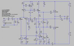
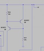
I usually clamp only the "second" VAS transistor (with BAT46, which appears to be a very good fit for the purpose), the one that connected to the drivers. If you connect the diode to the base of the first VAS transistor, as it was suggested, its nonlinear capacitance can worsen the HF THD. However, if you do like I said, you'd need a clamping transistor and a resistor (you'd need it anyway, for stability) in the emiitter of the second VAS BJT.
Surely limiting VAS input current directly limits slew rate though, as current is necessary below clipping to charge the driver parasitics.
Interesting point. Using a relatively slow VAS transistor like mje340, you need about 0.65 mA for 50V/uS, so Rb needs to be about 1K and the current limit at least 1.3mA. For a 50VDC rail that means a limiting resistor of 38.5K. So yes, you have a point, but preventing 10mA+ surge is still a good idea, and the current limiting resistor should be at least 10K.
I usually clamp only the "second" VAS transistor (with BAT46, which appears to be a very good fit for the purpose), the one that connected to the drivers. If you connect the diode to the base of the first VAS transistor, as it was suggested, its nonlinear capacitance can worsen the HF THD. However, if you do like I said, you'd need a clamping transistor and a resistor (you'd need it anyway, for stability) in the emiitter of the second VAS BJT.
I noticed this when I was designing for 1ppm THD. Notice that limiting the (2nd) VAS transistor is a good idea because VAS over current can happen at any voltage, not just at clipping.
A 1N4148 style small signal diode is not good enough if you are aiming for very low distortion. A BAS21J reverse capacitance is about 1.3 pF and the characteristic is quite flat - the NXP and Vishay types are best.
Yep.. I am behind the times. So many new interesting components around. Still, 1N4148/BAT46 are through holes, available almost everywhere in the world.
A small addition to the feedback provides ~flawless clipping recovery without using any clamping diodes.
I tweaked the VAS but the slew is actually limited by the FET gate capacitance and the lack of drivers and a limited VAS collector current. Running the VAS hot vs adding drivers vs limited slew (> 20KHz) is another discussion.
I tweaked the VAS but the slew is actually limited by the FET gate capacitance and the lack of drivers and a limited VAS collector current. Running the VAS hot vs adding drivers vs limited slew (> 20KHz) is another discussion.
Attachments
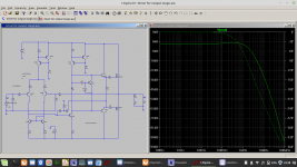
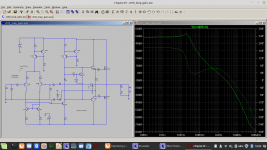
Same question by me - distortions drop significantly in simulation, specially at high frequencies. The only drawback I know is a slightly reduced max output level before clipping.
Also, why not add a driver stage for the MOSFETs rather than driving them directly from the VAS?
what are the options for a driver stage using mje340/350
please mod the attached file
Attachments
You disconnect the ac-signal source. Then probe the current into the driver/power stage. You know howto probe current in LTSpice?thanks voltwide.
what would be the procedure to set the FETs bias to 100mA and the driver stage to 10mA
With the .step command you test a series of bias setting resistor values and choose the best fitting at the end. For instance
.step param Rx list 1k0 2k2 3k3 4k7
steps the param "Rx" with 4 values.
The resistor to be stepped must have the value {Rx}
hope that helps
- Status
- This old topic is closed. If you want to reopen this topic, contact a moderator using the "Report Post" button.
- Home
- Amplifiers
- Solid State
- improving clipping behaviour