Hi! New to DIYAUDIO, so hoping you'll forgive if this is posted in the wrong place.
Was given a complete SAE system (A501 Amp, P101 Preamp, E101 EQ and T101 tuner) for free (including all the vintage manuals, schematics, service manual).
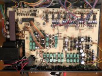
Pre-Amp has no sound through any output or headphone jack. Powers on and switches all seem to work. Opened it up and looked at the main board. Some glue around the capacitors, but in one section, some significant burning, and looks like someone has already been rooting around in there. See pics attached.
I'm moderately tech savvy, can operate a soldering iron and have a DMM. However, I'd need some handholding to repair, and will ask some dumb questions.
First questions: Repairable? Worth repairing? Or should I sell the pre-amp as is and get what I can for the rest of the system?
Thanks, in advance for your help!
Was given a complete SAE system (A501 Amp, P101 Preamp, E101 EQ and T101 tuner) for free (including all the vintage manuals, schematics, service manual).
Pre-Amp has no sound through any output or headphone jack. Powers on and switches all seem to work. Opened it up and looked at the main board. Some glue around the capacitors, but in one section, some significant burning, and looks like someone has already been rooting around in there. See pics attached.
I'm moderately tech savvy, can operate a soldering iron and have a DMM. However, I'd need some handholding to repair, and will ask some dumb questions.
First questions: Repairable? Worth repairing? Or should I sell the pre-amp as is and get what I can for the rest of the system?
Thanks, in advance for your help!
Attachments
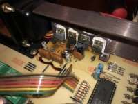
Certainly repairable. The burned area is part of the power supply, and really should be quite easy to fix. Problem is that there seems to be no manual/schematic available online and that makes talking someone else through a repair pretty tough.
Those 'filter caps' (the ones by the glue) sure don't look right. These are normally larger electrolytic caps. Beyond that, you could probably start out by removing all the components on the power supply section that is burned, and check the T0-220 transistor and the TO-92 transistor. Also look like a Zener diode in there - for now just test it as a standard diode. Might as well pull all the resistors too, noting what goes where. You are going to need to repair the board in that burned area.
Those 'filter caps' (the ones by the glue) sure don't look right. These are normally larger electrolytic caps. Beyond that, you could probably start out by removing all the components on the power supply section that is burned, and check the T0-220 transistor and the TO-92 transistor. Also look like a Zener diode in there - for now just test it as a standard diode. Might as well pull all the resistors too, noting what goes where. You are going to need to repair the board in that burned area.
Don't now about sound quality of this item, looks like someone has made an effort.
Yes there are some hot spots but that's expected to some point, the transistors are heat sink
mounted=expected to get hot. A basic health check of the power supply should be
performed. Regarding the missing audio, the sucker bet is one of the green relays or
associated control circuit has failed. You should try all audio inputs (tuner/cd/aux/tape...)
you might get lucky.
The immediate problem is to find the service manual/schematic, then you can
perform the power supply checks and lastly trace the audio...
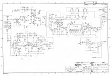
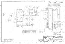
Thanks! I actually have all the schematics and the service manual, believe it or not. All attached here.
But from the sound of your replies, I'm starting to worry that this might be beyond my skills...doing a full diagnostic on it is probably something I'm not capable of.
I did check all the inputs - nothing.
But from the sound of your replies, I'm starting to worry that this might be beyond my skills...doing a full diagnostic on it is probably something I'm not capable of.
I did check all the inputs - nothing.
Attachments
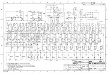
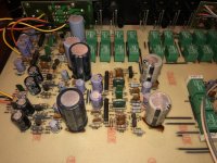
OK! Then let's start by checking out the power supply. Assuming you haven't started to pull those parts off the board yet.....
With the unit powered up, measure the voltages at the following:
Q12 right side terminal (also C60 positive terminal) should be +12 volts.
Q13 right side terminal (also C66 positive terminal) should be +5 volts
Either end of R76 should be about +28 volts. One end should be about 0.4 volts more/less than the other.
Positive end of C68 should be +17 volts.
Either end of R75 should be about -28 volts. One end should be about 0.4 volts more/less than the other.
negative end of C69 should be -17 volts.
Let's start with those measurements.
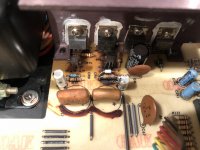
I just completed a re-cap on two(2) P101. The likely cuprit are these relays. Start taping the tops of them. If the are the ultra-sonic cleanable type relays. Remove the tops and spray contact cleaner. Use MG Chemical SUPER HFE (Cat.No. 4120-450G). This specific cleaner will allow you the spray live circuit, while listening to main output. See special note on page 13 of service manual.
Missed the 100ohm resistor and diode, could be track damage. Also could be
supply to opamps or relays so no audio.
I agree with this comment, R80 and CR11 not looking to good. Check for +28.x VDC on either side of R82.
- Status
- This old topic is closed. If you want to reopen this topic, contact a moderator using the "Report Post" button.
- Home
- Amplifiers
- Solid State
- SAE p101 Pre-Amp Problems