Hi. I own a few Hafler P9505 amps, and have just added a 9500 to the mix.
But this 9500 has some differences compared to the (9500) schematic I found on the web.
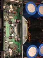
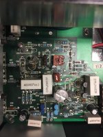
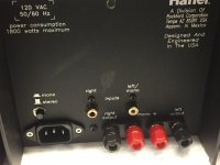
For one thing, there are more low-voltage power supply decoupling caps, both electrolytic and (polystyrene?) than the schematic shows. And there is a 1000uf/10 volt non-polar cap in each channel, which seems to be driven from signal at the output of the first transistor pair.
It's pretty good sounding, lots of detail, but highs and lows are a bit rolled off compared to my 9505s.
Questions:
Anyone have a schematic for this older version 9500 amp?
Can anyone recommend a way to fabricate (or buy) "daughter boards" to attach paralleled, lower value, low ESR caps to the PC board, where the 22000uF caps are bolted in? 28.5 mm spacing on the terminals.
On the P9505s I've replaced the output filter caps with longer Kemet units, and "leave the lid off" Too tight to try in this 9500, however. and moving forward it would be nice to put the lid back on my 9505s
I'm guessing the non-polar caps are for DC blocking in the audio, as opposed to a DC servo circuit correcting offset: I see no evidence of one...
Any ideas?
I'll replace these caps with Nichicon UES series ("MUSE) non-polars. One shows slight leakage at the vent, so it's probably not helping the frequency response....
Thanks in advance for any and all help.
This is a great forum for learning the "finest, pointiest points" about audio.
But this 9500 has some differences compared to the (9500) schematic I found on the web.
For one thing, there are more low-voltage power supply decoupling caps, both electrolytic and (polystyrene?) than the schematic shows. And there is a 1000uf/10 volt non-polar cap in each channel, which seems to be driven from signal at the output of the first transistor pair.
It's pretty good sounding, lots of detail, but highs and lows are a bit rolled off compared to my 9505s.
Questions:
Anyone have a schematic for this older version 9500 amp?
Can anyone recommend a way to fabricate (or buy) "daughter boards" to attach paralleled, lower value, low ESR caps to the PC board, where the 22000uF caps are bolted in? 28.5 mm spacing on the terminals.
On the P9505s I've replaced the output filter caps with longer Kemet units, and "leave the lid off" Too tight to try in this 9500, however. and moving forward it would be nice to put the lid back on my 9505s
I'm guessing the non-polar caps are for DC blocking in the audio, as opposed to a DC servo circuit correcting offset: I see no evidence of one...
Any ideas?
I'll replace these caps with Nichicon UES series ("MUSE) non-polars. One shows slight leakage at the vent, so it's probably not helping the frequency response....
Thanks in advance for any and all help.
This is a great forum for learning the "finest, pointiest points" about audio.
Attachments

Available at Elektrotanya: HAFLER 9500 SCH Service Manual download, schematics, eeprom, repair info for electronics experts
Hi Monte,
Thanks. I have this schematic and a slightly more legible version from this link:
http://www.audiodesignguide.com/doc/ampl/hafler_915c.jpg
However, it's not QUITE what I have here. This looks like an early version of the 9500 TransNova, maybe a "first draft".
A lot of the circuit is similar: same transistor count per channel in the input and driver stages , same output devices, but those non-polarized electrolytics, and their bypass caps, are not on the schematic....at 1000uf /10 volts, and their (apparent) signal feed from the first set of transistors, I'm guessing they are meant to block DC downstream of the input stage. But, without the schematic, I'm guessing.
(Earlier I stated that there was no DC servo in this amp: from what I can tell, there's no DC servo in the schematic of the later model 9500, either. Maybe this was incorporated into the 9503 and 9505 only)
Might require some happy hours with a scope, DMM, and the schematic you mentioned to figure this out....
Thank you for the information!
Best,
Ed
Thanks. I have this schematic and a slightly more legible version from this link:
http://www.audiodesignguide.com/doc/ampl/hafler_915c.jpg
However, it's not QUITE what I have here
. This looks like an early version of the 9500 TransNova, maybe a "first draft".A lot of the circuit is similar: same transistor count per channel in the input and driver stages , same output devices, but those non-polarized electrolytics, and their bypass caps, are not on the schematic....at 1000uf /10 volts, and their (apparent) signal feed from the first set of transistors, I'm guessing they are meant to block DC downstream of the input stage. But, without the schematic, I'm guessing.
(Earlier I stated that there was no DC servo in this amp: from what I can tell, there's no DC servo in the schematic of the later model 9500, either. Maybe this was incorporated into the 9503 and 9505 only)
Might require some happy hours with a scope, DMM, and the schematic you mentioned to figure this out....
Thank you for the information!
Best,
Ed
Hi Monte,
Thanks. I have this schematic and a slightly more legible version from this link:
http://www.audiodesignguide.com/doc/ampl/hafler_915c.jpg
However, it's not QUITE what I have here
A lot of the circuit is similar: same transistor count per channel in the input and driver stages , same output devices, but those non-polarized electrolytics, and their bypass caps, are not on the schematic....at 1000uf /10 volts, and their (apparent) signal feed from the first set of transistors, I'm guessing they are meant to block DC downstream of the input stage. But, without the schematic, I'm guessing.
(Earlier I stated that there was no DC servo in this amp: from what I can tell, there's no DC servo in the schematic of the later model 9500, either. Maybe this was incorporated into the 9503 and 9505 only)
Might require some happy hours with a scope, DMM, and the schematic you mentioned to figure this out....
Thank you for the information!
Best,
Ed
This is probably the same schem you've found.
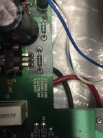
C9 in the schematic I posted is a non-polar 220uF in the feedback network. In your amp picture its labeled C109 (designates right channel) and is 1000uF. Either someone changed it at some point or it was a design change that was made and not reflected on the early schematic. The rest of your amp looks the same as the Hafler schematic from what I can tell.

Thank you, it IS C9 ( left channel, on the PCB silk screen) So this big brute is carrying feedback signal, then...wonder what difference a 220uF value would make; I'll try each value to see if I hear the difference. Original Illinois Capacitor part. Maybe that high value was deemed unnecessary for the load it was driving in the feedback path........
I'll re-cap and see what happens.
Do you see any evidence of DC servo circuit in the 9500 /9300 schematic? (9303 /9505 used an op amp for this (I think a TLO72 or 82) and a separate path back for this, but I can't find similar in this amp's schematic. definitely no op amps on board.
Thank you again. My version also has a few more low voltage power rail bypass caps, both electrolytic and film, than are shown on the schematics..
Best,
Ed
Thank you, it IS C9 ( left channel, on the PCB silk screen) So this big brute is carrying feedback signal, then...wonder what difference a 220uF value would make; I'll try each value to see if I hear the difference. Original Illinois Capacitor part. Maybe that high value was deemed unnecessary for the load it was driving in the feedback path........
I'll re-cap and see what happens.
Do you see any evidence of DC servo circuit in the 9500 /9300 schematic? (9303 /9505 used an op amp for this (I think a TLO72 or 82) and a separate path back for this, but I can't find similar in this amp's schematic. definitely no op amps on board.
Thank you again. My version also has a few more low voltage power rail bypass caps, both electrolytic and film, than are shown on the schematics..
Best,
Ed
The 220uF cap would shift the low freq -3dB point higher. 1000uF will put this cutoff freq very close to DC. I think that your 1000uF was installed from the factory. I have an older series Hafler XL600 and it uses a 1000uF/6.3V in this location.
There is no DC servo in your early model so the complimentary input pairs must be well matched to avoid DC offset.
The electrolytic capacitor count is correct with the schematic I posted unless there's something that isn't showing in your pictures.
Last edited:
The 220uF cap would shift the low freq -3dB point higher. 1000uF will put this cutoff freq very close to DC. I think that your 1000uF was installed from the factory. I have an older series Hafler XL600 and it uses a 1000uF/6.3V in this location.
There is no DC servo in your early model so the complimentary input pairs must be well matched to avoid DC offset.
The electrolytic capacitor count is correct with the schematic I posted unless there's something that isn't showing in your pictures.
Thanks. I miscounted the electrolytics; they do match your schematic.
Since the 220uF cap will raise the LF -3dB point, I'll stick with 1000uf non polarized as a replacement. Wonder why it's value was later reduced that much
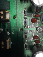
(Interestingly, the 4.7 uF bypass caps on this amp's "HV output" rails are branded "Musical Concepts PPB": they're longer, and have a higher voltage rating (250V) than the Illinois Capacitor metalized polypropylene models I find in the P9505s. There's an extra eyelet on the PCB to accommodate either size)
Thanks for confirming the lack of a DC servo circuit: I had noticed that on this older model (and an early P9505 I have) each pair of input transistors have a dab of the same paint color on their tops, indicating (I guess) they were factory matched. Not so in later P9505s....
Painfully obvious oversight ....
I stated in my previous post that Hafler 9500/early 9505s had matched input jfet transistor pairs, factory marked with paint, but those disappeared from later 9505s.
Well, I had another look at two of my "newer" 9505s:
The reason is because those discrete jfets seem to have been replaced in later model amps by surface mount jfet pairs: National Semiconductor NPDS 5566 chips, rather than discrete devices, are present in my two later model P9505s.
Anyone have a schematic for the late model (surface mount component) version?
I have several 9505 schematics, latest from around 1994, but none show the SMD version of the amp.
- Status
- This old topic is closed. If you want to reopen this topic, contact a moderator using the "Report Post" button.
- Home
- Amplifiers
- Solid State
- Help with Early Hafler 9500