Having perused as many Citation 12 threads as I can find looking for a answer i have decided to post it up here.
Most of the threads are aged. They discuss the Pass Mods mostly which at that point it's something other then a Citation by H/K. I have been hoping to not go that route. This Amplifier sounds great as is when playing. First fired up by me it crackled loudly on power up. I have been looking at Variacs since then. Over time it has diminished to a small crackle which persisted on power off on the left channel only. The right channel is quiet on power up or down with exception of the mild thump this type of topography is known for. That is not bothersome.
My attempts to quiet the crackle proceeded to do a electrolytic replacement. First the Power caps and input coupling caps on the chassis. C1,C2, C3,C4,C5,C6, It went well but the crackle persisted.
Next were the 8 caps on the main board. This entails another lesson. Before replacing them had I had enough light to see the cracked resistor, 27ohm 2w
R738. It was the only resistor on the board with a gold band which tells me it had already been replaced once.
I got real lucky and found a direct replacement. I had already replaced all the Ecaps. c703 & 4, C705 & 6, C707 & 8, C 711 & 12,
After replacing all this I adjusted the bias to 30mv. As close to 29.6 as I could. Did the crackle go away? no.. Just the left side. but it plays great and sounds superb.
Of note are the bias pots positions are much different. The right channel is 3/4 across the range. The Left channel, with crackle is only 1/4 across the range.
While playing I feel heat coming from one output transistor. I make it out to be Q4, which gets its input through R736.
This is where I seek some guidance. looking at the schematic is there a likely suspect heating up both Q4 and R738, which goes to ground.
The trim pot is also in this leg which is also getting it's voltage from Q3. My first suspect is R732. Any other suspects? I have yet to take voltage readings. Thanks to whoever may assist.
While the recap will be of some benifit, the shotgun parts replacement is not a good
troubleshooting technique. The freeze spray is a good idea, an oscilloscope would be handy
alternatively an audio probe (old MM probe with 1uf/400V? series cap) may help.
Suggest fit a speaker protection kit, basic units can be had for about USD8 on the
bay/china, probably need a mains(110Vac?)/12V/1VA transformer, another USD6
llwht thanks for the reply. I agree time to test will be not long. Biggest problem is access on trace and solder joints. A oscope and freq generator are on the list. I suspected this would be necessary and actually fun. Time is short so for now I am listening to it and expecting some burn in improvement. It is testing it as well.
wiseoltech..emphasis on the wise. you are so right. Thanks for the reminder. I kind of did that with the trim pot. It also drew me to hope someone with more skill then I, could narrow down probabilities.
mbz. Process of elimination. I had the parts ordered/delivered. Planned replacement. Didnt shotgun anything. One of the big Mallorys was weeping so it seemed prudent to replace the lot of them. At the same time the two filters on the input were right there. I also at the same time replaced the ugly RCA input jacks with a couple bright shiny gold plated jacks. It was the toughest part. When the crackle persisted I replaced the main board caps which were testing out of specs. Do one do em all while you are in there.
After that testing output voltages and offset showed a big difference, and having replaced the bad resistor which I did not see up front I had hope. These were going to go anyway.
"an audio probe (old MM probe with 1uf/400V? series cap)" Not familiar with this. Can you explain?
The speaker protection kit is good advice. I looked into them a bit. Will revisit. I hesitate to add more connections in the music path. Plus as you point out it needs additional power to operate the relays. Am setting up to fuse speakers. Still want to correct the problem. Thanks for your time.
Mark ... No spray. Will add it to the next order. Maybe one of the smaller input transistors could be producing the crackle. Could put the board in the freezer in the meantime. I intent to take it back off to test all the components. Is is likely a transistor or a diode, but the higher voltage points to a resistor.. I think..... Thanks again to all. Hoping someone familiar with this amp could weigh in.
mbz. Process of elimination. I had the parts ordered/delivered. Planned replacement. Didnt shotgun anything.
"an audio probe (old MM probe with 1uf/400V? series cap)" Not familiar with this. Can you explain?
The speaker protection kit is good advice. I looked into them a bit. Will revisit. I hesitate to add more connections in the music path. Plus as you point out it needs additional power to operate the relays. Am setting up to fuse speakers. Still want to correct the problem. Thanks for your time.
.
Glad to hear no shotgunning
The idea behind the audio probe is to simply probe/test/siphon off audio at
various stages (eg transistor bases) to work out where the fault is introduced.
You will need a probe, typically old MM probe, a film DC blocking cap, say
1uf/400-1000V. Connect cap in series to probe, the other end of the cap
goes to an RCA connector which plugs into another amp that amplifies what
the probe picks up. You need to keep in mind the expected signal level as to
where you plug in the RCA, either MAIN-IN for power amp issues and
AUX for pre issues.
The speaker protection kit will provide power on/off mute as well as dc
protect. Only a few provide over current.
Getting me thinking. New concept to me on the probe. Thanks
Many of the problems I see here are 1/2 hour jobs at best but seem to take forever because nobody has any test equipment other than a meter of some sort. A signal generator and o'scope are a MUST. I guess that's why this is DIY.
Craig
Indeed, attempting to work without the proper tools is just nonsense.
And utterly unsuccessful, waste of time.
This then generates 1,000 replies back and forth in threads, with nothing accomplished.
You need a tire iron to remove the tires from your car, why babble online about it?
Additionally, knowledge and experience are needed - electronic theory, the Ohms Law, resistor color codes, etc.
But these days, everyone wants to do things "on the cheap", without all that horrible and tedious learning involved.
Good luck with that!
If you want to go fishing, you buy a boat, or drown.
Many of the problems I see here are 1/2 hour jobs at best but seem to take forever because nobody has any test equipment other than a meter of some sort. A signal generator and o'scope are a MUST. I guess that's why this is DIY.
Craig
Another issue is that many here do not understand the concept of trouble shooting. You see posts like : 'I have DC on the speaker. Should I replace the power supply capacitors, they are 15 years old'.
Jan
Having perused as many Citation 12 threads as I can find looking for a answer i have decided to post it up here.
Most of the threads are aged. They discuss the Pass Mods mostly which at that point it's something other then a Citation by H/K. I have been hoping to not go that route. This Amplifier sounds great as is when playing. First fired up by me it crackled loudly on power up. I have been looking at Variacs since then. Over time it has diminished to a small crackle which persisted on power off on the left channel only. The right channel is quiet on power up or down with exception of the mild thump this type of topography is known for. That is not bothersome.
My attempts to quiet the crackle proceeded to do a electrolytic replacement. First the Power caps and input coupling caps on the chassis. C1,C2, C3,C4,C5,C6, It went well but the crackle persisted.
Next were the 8 caps on the main board. This entails another lesson. Before replacing them had I had enough light to see the cracked resistor, 27ohm 2w
R738. It was the only resistor on the board with a gold band which tells me it had already been replaced once.
I got real lucky and found a direct replacement. I had already replaced all the Ecaps. c703 & 4, C705 & 6, C707 & 8, C 711 & 12,
After replacing all this I adjusted the bias to 30mv. As close to 29.6 as I could. Did the crackle go away? no.. Just the left side. but it plays great and sounds superb.
Of note are the bias pots positions are much different. The right channel is 3/4 across the range. The Left channel, with crackle is only 1/4 across the range.
While playing I feel heat coming from one output transistor. I make it out to be Q4, which gets its input through R736.
This is where I seek some guidance. looking at the schematic is there a likely suspect heating up both Q4 and R738, which goes to ground.
The trim pot is also in this leg which is also getting it's voltage from Q3. My first suspect is R732. Any other suspects? I have yet to take voltage readings. Thanks to whoever may assist.
Post the schematic that you're using.
Are the outputs the correct type?
Electrolytics capacitors seem to be the magic elixir on these forums. Troubleshoot the problem and if turns out to be a capacitor that's fine but at least you know what fixed the problem.
As for the crackling sound my first guess would be to re-seat the driver board, maybe clean the connectors while you're at it and check for broken solder joints. If that doesn't do it then the input diff transistors, Q701/702, would be next on the list. The 12 came in two versions, one with a dual transistor package and one with two discrete transistors. There are new dual transistors still available but mostly NPN and expensive, you need PNP type. Two KSA992 transistors should work OK here.
For the hot output transistor, have you checked for DCV on the speaker terminals? Should be close to 0VDC. Then check the voltage across the the emitter resistors, .008-.013VDC across each, where did you get 30mv? R737/738 shouldn't come into play unless the amp is oscillating or you are testing full output at very high frequencies.
Craig
Electrolytics capacitors seem to be the magic elixir on these forums. Troubleshoot the problem and if turns out to be a capacitor that's fine but at least you know what fixed the problem.
As for the crackling sound my first guess would be to re-seat the driver board, maybe clean the connectors while you're at it and check for broken solder joints. If that doesn't do it then the input diff transistors, Q701/702, would be next on the list. The 12 came in two versions, one with a dual transistor package and one with two discrete transistors. There are new dual transistors still available but mostly NPN and expensive, you need PNP type. Two KSA992 transistors should work OK here.
For the hot output transistor, have you checked for DCV on the speaker terminals? Should be close to 0VDC. Then check the voltage across the the emitter resistors, .008-.013VDC across each, where did you get 30mv? R737/738 shouldn't come into play unless the amp is oscillating or you are testing full output at very high frequencies.
Craig
I agree on that procedure.
And as for replacing the differential pair as matched seperates (an upgrade bulletin), I'd hug them together physically, maybe with a spot of thermal grease and a zip tie.
Post the schematic that you're using.
Are the outputs the correct type?
Yes i intended to but have only found linking to a hosting service which i do not use any.
It is readily available on Hi Fi Engine which gave me the confidence to point out certain components.
The weekend is not my own so was unable to address this. of course we had a storm knock out power today so it was lost. Can a PDF be just uploaded?
Electrolytics capacitors seem to be the magic elixir on these forums. Troubleshoot the problem and if turns out to be a capacitor that's fine but at least you know what fixed the problem.
As for the crackling sound my first guess would be to re-seat the driver board, maybe clean the connectors while you're at it and check for broken solder joints. If that doesn't do it then the input diff transistors, Q701/702, would be next on the list. The 12 came in two versions, one with a dual transistor package and one with two discrete transistors. There are new dual transistors still available but mostly NPN and expensive, you need PNP type. Two KSA992 transistors should work OK here.
For the hot output transistor, have you checked for DCV on the speaker terminals? Should be close to 0VDC. Then check the voltage across the the emitter resistors, .008-.013VDC across each, where did you get 30mv? R737/738 shouldn't come into play unless the amp is oscillating or you are testing full output at very high frequencies.
Craig
Whole sale changing capacitors is not my religion by any means. In fact I am of the "if it ain't broke don't fix it" class. Always have been a minimalist.
I did wipe all the posts with D5 before install and have found only on solder connection needing doing. It was off the transformer and was wrapped on the negative rail on the power caps. It may have been ok but it is ok now.
I was not 100% confident of the seating and did give each connector a push from both sides and a couple may have moved. The bottom of the board is tight on the chassis. It will get a better inspection and re-connection when it hits the bench.
Thank you for this. Will get back to you on it. "If that doesn't do it then the input diff transistors, Q701/702, would be next on the list. The 12 came in two versions, one with a dual transistor package and one with two discrete transistors. There are new dual transistors still available but mostly NPN and expensive, you need PNP type. Two KSA992 transistors should work OK here."
It was what I was hoping to get.
I initially check voltage on the speaker outputs. The right channel was much lower then the left side. The right side was unsteady from about 8 to 17 MV.
Will retest and post. On emitter voltage on Q 701 on the right board & 702 on the left board... i have photo's of board to ID it.
Where did I get the Bias voltage.... Good question. Off the internet so it......
I searched for a couple hours yesterday but was unable to reproduce the source but as I recall it's a calculation based on .008vdc-.013vdc measured using 200mv on digVM. It was doable. I did not cipher it out.
I hope to find the reference.
Thanks again. "I'll be back".
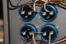
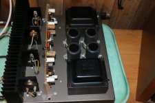
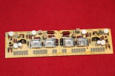
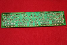
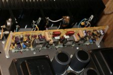
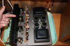
Lets try this again. Ok 1 is weepy mallory 2 is replaced Power caps 3&4 is original board front & back. 5 Installed recapped. 6 is Hot output. I think the bias pots are pretty much where I found them and the resistor on the output .. you can see the crack. i missed it till after I changed caps.
Notice too all transistors are silver tolerance band cept this one is gold. telling me it has been replaced once.
Notice too all transistors are silver tolerance band cept this one is gold. telling me it has been replaced once.
Attachments
Last edited:
From the looks of those filter caps, they should be replaced.
Once one pops its seal, they'll all need replacing.
And time to check all the on-board caps as well..... IF you want reliability......this thing's decades old already.
Done. Its all in the pictures. Glad you agree.
- Status
- This old topic is closed. If you want to reopen this topic, contact a moderator using the "Report Post" button.
- Home
- Amplifiers
- Solid State
- Hot Output on H/K Citation 12