I need an advice for vintage power-amp modules LV70-II
from the early 70ies. These have been developed by
Musikelektronik Geithain in the former GDR for
different non-commercial purposes.
It is a quasi-complementary design with Tesla
KU605 and RCA 2N3773.
Despite of the weaknesses of this old design,
I like the sound. Also I have several of theses modules
and would like to use them. I have a good tech that
already worked on these amps, but he is not specialized
in this field. He experienced problems with the
stability of the amp: A non compressed bias (hope
this is correctly translated), time offset which leads to distortion
at low levels. Also thermal coupling (T4 - bias current generator
with T14) not optimal.
Any insights are highly welcome! I will be in touch with my tech
about it and hope that I can react in a short time.
Attachments
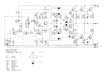
R5 the bias control pot, could lose contact with the wiper and allow idle current on the OT's to run away. I'd parallel it with a schottky diode to clamp it to .3 v, if that allows enough bias current.
I'd also increase OT emitter resistors from .3 ohm to .47. I'd put one in the emitter leg of T14; Apex AX6 has one and it doen't hurt anything.
The 100 uf C8 may lead to the time delay in the bias control network. Look at various apex designs for something similar but more effective. Also change T4 to a heat tab transistor, say a BD139, and screw the tab to the output transistor heat sink with an insulator. Don't run the heat sense wires close parallel to the driver wires, this could cause oscillation.
If the amp tends to oscillate, changing C9 from 47 to 68 pf might help. Make sure it is a COG disk cap or a silver mica, not a wound plastic film cap.
Last edited:
indianajo, here is the reaction to your reply:
1. "R5 the bias control pot, could lose contact with the wiper and allow idle current on the OT's to run away. I'd parallel it with a schottky diode to clamp it to .3 v, if that allows enough bias current."
R5 is not the bias control pot, but the gain-adjustment.?
2. I will check your hint concerning C8
3. I will also check your info to C9 and will test the changes concerning this C9.
4. BD139 as driver: This has brought the best result yet. The problem is, that BD139 is allowed for only 80 Volts current. When idle, more than 80 Volts are present. I have to think about it again...
Sorry, that might be R9 as the idle current pot.
I wouldn't monkey with C9 unless you get actual oscillation. This tends to happen when the amp clips in a lot of designs. Test also with a square wave source, this tends to drive marginal amps into oscillation, at least for a while. Don't overheat your speakers with square waves, use a load resistor for testing.
The schematic is saying 40409 and 49410 as drivers. I had some of these, I don't have a datasheet & I'm vague about whether they were the specially selected TO5 parts (2n2102), or the specially selected TO3 (2n3055 base) parts. I'm still running the genuine RCA TO5 parts as drivers in my ST120; they are faster than anything I can buy with the same EBC pinout. On semi MJE15032/33 will work, are plenty fast, have high enough voltage but have the wrong pinout and have to have the legs twisted around.
As for the bias capacitor C8, look at the index of Apex amps for an amp with the drivers run off the rails, then look at his idle current control networks. His amps are usually well thought out and reliable.
The diyaudio honeybadger by ostripper uses a 22 uf cap on the idle current control transistor Q13, and his network is simpler than this also. That is a state of the art class AB amp IMHO.
Last edited:
Just luck I was quick this time. I spend 4-5 days a week at my summer camp off the internet. Much less ozone out there 400 feet higher. In town to see the dentist today.Thank's again for your quick reply! More soon...
Others with more knowledge are welcome to contribute.
First you should copy the schematic into spice and download any transistor models you are missing. Then you can try and tweak any changes to see if they actually improve the amp before you risk any loses and wasted time and parts.
Then there are a few obvious things that you could try and a others that are difficult decisions.
1. The output is a qusi-comp 3EF which I quite like but you need to decide if it's worth converting to fully complimentary (+PNPs) and cross coupling. I would probably leave it as is.
2. The protection circuit is VI which may be an issue in certain applications. Again, I would probably leave it as is.
3. It uses bootstrap VAS load and you may want an active current source. I would leave it.
4. The diff-amp (LTP) uses a passive current source. Again, you may want active. I would not go active but I would add a diode in series with R15 to improve start-up thumping.
5. I would replace R10 with a current mirror but this may require increasing C9 to maintain stability with the extra loop gain, lower THD. A current mirror also greatly improves thumping.
6. Replacing/adding a Darlington to the VAS (T3) should improve THD significantly, but again be careful about stability.
7. I would minimize R14 and decouple T3 emitter to a separate signal ground. In fact signal ground should not be mixed with the ground from C4; C5, and R24;R25. Perhaps you could separate pins 11 and 12 and wire them separately back to the power supply.
8. C3 is some kind of hack that should be investigated. Remove it if possible.
9. R2 should match R7 and with a current mirror to balance the diff-amp (TLP), R3 could be replaced with a a pair of fixed resistors (220 Ohms). In any case the danger of R3 failing could create a huge +DC output so I would add (two ~2.2k) bypass resistors around R3 if you don't remove it.
The use of 22 Ohms resistors on the bases of the 2n3773s tells me that this designer knew what they were doing. So I feel like you have to decide to completely replace the amplifier with a modern design using modern parts or make minimal changes.
1. Seasound, your tech is definitely right when it comes to T4 - this should be attached to the heatsink, maybe with thermal glue/epoxy. Its wires should be kept close together and away from the rest of the circuit, this being a relatively high-impedance node. Wait, I think the bootstrapping would affect (diminish) any stray capacitance as well, so I guess there's one argument for sticking with the oldschool bootstrapped emitter load.
2. A quick calculation of bias circuit voltage indicates an adjustment range between "somewhat underbiased" and "nuclear meltdown". This may make bias adjustment overly touchy, even when the pot is not 40+ years old and corroded. Not sure why they did it like that. Besides, no idea what R8 is supposed to accomplish - some sort of failsafe in case R13 burns up?
3. While I don't mind quasicomp output stages per se, there are a few things I would improve about it:
a) Add Baxandall diodes between emitter of T10 and R34 (polarity matching T10 obviously), so as to mimic pnp equivalents of T11 and T13. (This makes the two output stage halves more symmetrical.) Bonus points if you are able to match the KU605 and 2N3773 emitter junction well. I guess I'd use BC337 and BD139/BC639 wired as diodes (connect B-C), and thermally attach them to the heatsink so you don't lose bias stability. (If heatsink mounting TO-92s is too annoying, I'd just use two BD139s instead.) Amazingly enough, the stock bias circuit should still work for this mod. (Fiddling with R11 and R12 to give a more sensible adjustment range afterwards is probably a good idea.)
b) R33/34 being 0.3 ohms is a bit on the high side by hi-fi standards. I would want to reduce that... maybe 0.15 ohms. This ideally requires modifying overcurrent protection as well, but if that is planned anyway it would be a good opportunity to do both. With the lower resistor value, ideal bias current would go up (about 90 mA), but with the bias circuit being modified (1.) you can probably afford that.
4. Does the amplifier contain the now-customary RC Zobel network and series output inductor somewhere else? These were not yet standard at the time but potentially help with stability a lot.
5. Electrolytics have probably been changed at this point. Teslas could be really bad.
I would also direct my attention to some things not shown in the schematic:
1. PCB layout. Look at high current paths (e.g. +Vs - output - output ground return - power supply section) and their loop area. The smaller, the better. (That's why wiring between power supply and amplifier is twisted nowadays.) This being in early-'70s design, I would be prepared for the worst, but as they say, hope springs eternal.
2. I cannot seem to find much on what kind of inputs this thing uses (unbalanced? transformer balanced?) or its grounding concept.
Last edited:
Philips patent.Besides, no idea what R8 is supposed to accomplish - some sort of failsafe in case R13 burns up?
Be careful with the Baxandall diode, it can sometimes cause oscillation in output stage.
Then lower driver will need a cap between base and collector.
I designed a very similar amp and didn't put local decoupling on the power rails.
The first time I turned something off the glitch on the mains blew up the amp.
So maybe 100uf and 100n close to output transistors.
I also found I needed a couple of ohms degeneration between driver transistors and output transistors to stop oscillation.
Sgrossklass, all capacitors have been renewed. At the moment there is the original transformer balanced input which sounds good but has it's disadvantages (impedance problems, distortion). I am going to test an electronic balanced input-curcuit soon.
Also to mention is the completely renewed power-supply with toroidal transformer, high-quality capacitors and fast diodes.
Also to mention is the completely renewed power-supply with toroidal transformer, high-quality capacitors and fast diodes.
- Status
- This old topic is closed. If you want to reopen this topic, contact a moderator using the "Report Post" button.
- Home
- Amplifiers
- Solid State
- Advice for improving professional vintage GDR power-amp