As you had seen ? SS relay is what is used to switch the speakers signal.How about using a SS relay, I have seen one here on the Diyaudio website that has 0 distortion.
btw: 0 distortion don't exists: the all have a (low) non linear serial resistance.
I don't know if some MOSFET static relay exists able to afford the peak voltage of a 250V AC line.
The part noted as expensive was, I think, chosen by Esperado to limit easily the signal for the LEDs that fire the original Triac static relay (Isolation).
As long as you allow only 12V signal for the remote and a 12V relay, you can replace this part by a wire and even suppress the diode's bridge before it.;-)
And forget to populate the whole remote parts, if some don't need any remote of power on function:
it is mostly useful for active speakers.
As well as you could forget silent stop: the protection itself will do the job anyway. It is just a little faster with it.
Last edited:
It's all relative to the distortion level and profile of the amp. If the SSR adds no discernible and measurable distortion to the amp's distortion, then for that context I guess one can say it's "zero" distortion, no?btw: 0 distortion don't exists: the all have a (low) non linear serial resistance.
https://www.diyaudio.com/forums/showthread.php?p=5897082
Shouldn't be a problem getting 400V or higher rated MOSFETs with the ultra-low Rdson needed.I don't know if some MOSFET static relay exists able to afford the peak voltage of a 250V AC line.
Higher voltage MOSFETs necessarily have more on-resistance due to the lower doping levels in the drain. Power MOSFET - Wikipedia
Then maybe a actual relay or SS system could be made and the builder choice as to which one to use. One more question, if a zero crossing detection circuit is used to power up the transformers in the power supply, does it generate any unwanted noise or such, that would deteriorate the entire amp and its systems? The same for using an Arduino or other micro based system. KiCad is great so far. Any KiCad users out there that have models and footprints for the ECW 20N/P20 in plastic cases? If not I will make some. What 400V MosFets with Ulow Rdson could be recommended ?
Thanks
Thanks
Krisfr, What are-you refering to ? The protection relay ? If yes, the Mosfet chose by Esperado seems among the best available.Then maybe a actual relay or SS system could be made and the builder choice as to which one to use. One more question, if a zero crossing detection circuit is used to power up the transformers in the power supply, does it generate any unwanted noise or such, that would deteriorate the entire amp and its systems? The same for using an Arduino or other micro based system. KiCad is great so far. Any KiCad users out there that have models and footprints for the ECW 20N/P20 in plastic cases? If not I will make some. What 400V MosFets with Ulow Rdson could be recommended ?
If you refer to the AC relays, forget: mechanical ones IS the solution, both on an economical and technical point of view: simple is beautiful, same than a 'power on' ordinary switch/button. And if they fail with age, just we have to replace them in a snap (plugged in a base connector). Car ones will be perfect.
About triacs, forget them. It is not such a problem of 'conduction', because once caps will be charged, the diodes of the rectifiers will conduct currents at a higher voltage level than the Triacs. It is just that, as the triacs will switch at some 5 volts, with a fast edge, it can generate a *mechanical* noise (buzz) in the transformer's coils, if the wires are not perfectly glued together.
No need to lose time on this.
As current is 90° out of phase with inductive loads (trafos), zero crossing voltage detection circuit seems the worse that we should use.One more question, if a zero crossing detection circuit is used to power up the transformers in the power supply, does it generate any unwanted noise or such, that would deteriorate the entire amp and its systems?
Certainly true.
You can switch mains toroids with TRIACs with negligible hum by driving the gate with "continuous" current of 20~50mA. I did this with 3x 2kVA toroids in the eighties. The "continuous" current was generated from NE555 oscillating at 30kHz and coupled through some standard gate drive transformer. Worked like a charm...
You can switch mains toroids with TRIACs with negligible hum by driving the gate with "continuous" current of 20~50mA. I did this with 3x 2kVA toroids in the eighties. The "continuous" current was generated from NE555 oscillating at 30kHz and coupled through some standard gate drive transformer. Worked like a charm...
If you have some kind of inrush current limiter, then it makes little difference whether you connect the mains to the (primary + ICL) at the best possible time or the worst possible time. In both cases the ICL will do its job and limit the inrush current according to your design objective.
On the other hand, a motivated designer could easily install a simple RC delay network at the appropriate point in the circuit, which causes the mains to be connected to the (primary + ICL), exactly 4.5 milliseconds after the zero crossing. This is a phase shift of 81 degrees in 50 Hz systems, and it is a phase shift of 97 degrees in 60 Hz systems. You'll be switching at approximately the mains voltage peak; remembering "ELI the ICE man" from university, this corresponds to the zero crossing of the mains current. Since the cost is so low, why not go ahead and put it in?
_
I went to Digikey, to the discrete MOSFETs page, selected Id continuous current rating between 25A and 42A, Vdss between 300V and 500V, and Rdson of 100 mOhm or lower. Selected only "normally stocking" and "active" products.Higher voltage MOSFETs necessarily have more on-resistance due to the lower doping levels in the drain. Power MOSFET - Wikipedia
I got 26 parts.
For me, that's plenty of choice.
Ya, if you want to stay below 10 mOhm, there are few choices. But then if we're talking about 10A continuous (or almost continuous), that's not a domestic amp, that's a sound reinforcement pro amp, right? And if 10A is just peaks, then we can get there with just PCB copper as heatsink, can't we?Indeed, but those are high on-resistances compared to low voltage MOSFETs. If you want to switch 10A without heatsinking you'd like 5 milliohms or so, 15A then 2 or 3 milliohms, all feasible at lower voltage.
... Of course, with the same printed board, changing some components values, it will always be possible to build a CFA amp with a more conventional OLG.(See attached)
As it is the opposite of the purpose of this project, I let the self-proclaimed gurus of this forum the task of demonstrating their mastery and proposing their optimized version in this direction.
As it is the opposite of the purpose of this project, I let the self-proclaimed gurus of this forum the task of demonstrating their mastery and proposing their optimized version in this direction.
Attachments
Could you pls be a bit more specific and list the persons you want to attack?I let the self-proclaimed gurus of this forum the task of demonstrating their mastery and proposing their optimized version in this direction.
Very well put. I know what you mean.If you don't agree with something, move on and go start your own thread. At least that is my thought. But if you can help, please do it and don't say "I know how" but I want you to show me if YOU can.
In another thread, I asked one of the posters to please explain one of his comments, and he responded with: "Search for the word "because" and then read that paragraph two or three times." I feel sorry for people who get their jollies from responding this way.
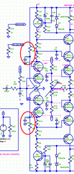
Krisfr, may-be it should be a good idea add those two resistances and two caps to the input stage ? The purpose is to reduce the collector voltage (power dissipation) of the first emitter follower.
A good practice should be to set the R values to match the collector voltages to the ones of the collectors of second stage amplifier transistors, when it is set with the casode.
If the cascode do not provide obvious benefits on AC results, it helps to give more latitude (power margins) on input stages currents, hence more choices of input transistors.
BTW, I'm on the same learning tracks than you, trying to switch from LTSPICE to MICROCAP ;-)
PS: To voltwide: I wonder how you can know better than me what *i* think by inferring intentions that I do not had.
Anyway, your ad hominem post, not really friendly as most of your previous ones, was both out of topic and an invitation to violate the forum's rules, reason why i did not answered as I will not answer to any other of the same kind.
I wanted to try the Dadod OITPC compensation. The occasion to set a more traditional version of this amp for a CFA: IE extended flat OLG up to 10KHz.
Here the results.
For OITPC, as I had not found a clear explanation of how to make calculations, I did-it by trying and groping.
it uses, apart the compensation, exactly the same schematic, only some resistances and caps values changed.
Krisfr, you can use this schematic for the paths as it is populated with all the options. Distortion is without "Error correction" (Amp alone).
Attachments
The pack won. I unsubscribe and leave this place too badly attended.
Is your decision irreversible?
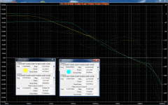
The two versions comparison.
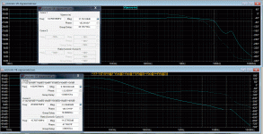
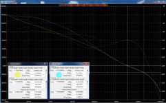
The V one, VFA like (blue), offer more gain at low frequencies (Less distortion up to iKhz, more damping factor ). The C version, traditional CFA like) a flat open loop gain up to 10 KHz, faster slew rate. The two versions will use the same printed board, sharing most of the components.
Just a little change of 8 resistances values and 3caps. I suggest them to be in through holes for an easier swap.
As previously said, the purpose is to can figure out what matters more and how each version will impact listening results. And if the 10dB distortion reduction provided by the optional error correction will modify-it. Simulated results promize both versions to be in the top league. I will publish soon the two sim files, after everything deeply verified.
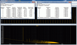
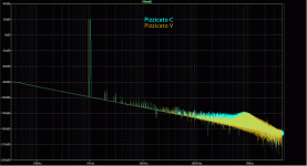
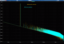
Comparison of HD with error correction.
Mistake with the colors, I inverted the colors with the previous image.
I apologize.
The last version V (Vfa like)
10Khz, 100V P.P.:
Without error correction: Total Harmonic Distortion: 0.000695%(0.000697%)
With the error correction: Total Harmonic Distortion: 0.000323%(0.000305%)
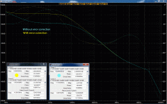
See (attached) the loop gain curves of the two options, with and without EC.
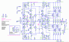
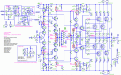
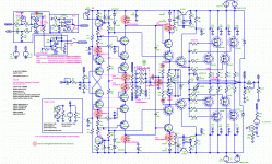
Krisfr, you can use this one as definitive for your printed board in progress .
.
The schematic is not going to change any more. In red, the values that gonna be different between the two versions.
The V one, VFA like (blue), offer more gain at low frequencies (Less distortion up to iKhz, more damping factor ). The C version, traditional CFA like) a flat open loop gain up to 10 KHz, faster slew rate. The two versions will use the same printed board, sharing most of the components.
Just a little change of 8 resistances values and 3caps. I suggest them to be in through holes for an easier swap.
As previously said, the purpose is to can figure out what matters more and how each version will impact listening results. And if the 10dB distortion reduction provided by the optional error correction will modify-it. Simulated results promize both versions to be in the top league. I will publish soon the two sim files, after everything deeply verified.
Comparison of HD with error correction.
Mistake with the colors, I inverted the colors with the previous image.
I apologize.
The last version V (Vfa like)
10Khz, 100V P.P.:
Without error correction: Total Harmonic Distortion: 0.000695%(0.000697%)
With the error correction: Total Harmonic Distortion: 0.000323%(0.000305%)
See (attached) the loop gain curves of the two options, with and without EC.
Krisfr, you can use this one as definitive for your printed board in progress
The schematic is not going to change any more. In red, the values that gonna be different between the two versions.
Attachments
And, to conclude, the C version (CFA-like).
Pros: Flat OLG up to 10 KHz, very high slew rate.
Con: Increased distortion in low frequencies, little less damping factor.
That's all, folks.
Pros: Flat OLG up to 10 KHz, very high slew rate.
Con: Increased distortion in low frequencies, little less damping factor.
That's all, folks.
Attachments
- Status
- This old topic is closed. If you want to reopen this topic, contact a moderator using the "Report Post" button.
- Home
- Amplifiers
- Solid State
- Pizzicato, a 200W low distortion CFA amplifier


