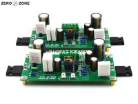
I purchased a pair of these kits: PASS-AM V15 Class A by Zerozone.
I have a dc offset at more than 100mV on both of the amps, and I'm not so happy with that.
I would like to be able to adjust that, but I'm not sure where the correct place would be to add a trimmer? Hope somebody can help?
Attached is a schematic I found on the internet and a picture of the boards. I'm not sure the schematic is 100% correct, but it seems to match pretty well regarding number of components and values.
I thought this was a push/pull, but it seems only one of the big transistors are 'drivers' and the other is a current source?
The advertised name refers to mr Pass, but I don't know which amp they cloned in that case?
Suggestions are welcome!
Attachments
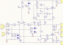
If Q4 and Q5 were matched, that is one way to clear the error or use a 2M2 resistor and a 100K pot. The 100k pot sits between the + and - rails. The wiper has one end of the 2M2 resistor, the other end, of the 2M2 resistor to the gate of Q4.
This will provide an offset for the error and help reduce it.
Horrible circuit in my view!
This will provide an offset for the error and help reduce it.
Horrible circuit in my view!
Last edited:
Thank you for the reply!
Strangely both are positive offset of abt 100mV, that makes me think it is unlikely to be just Q4/Q5 matching, since both seem to have almost the same mismatch?
If I do the potentiometer-mod, what are the downsides?
Strange circuit to me too, even if I don't get half of it.. Could R3 be used to set the current? I'm thinking of supplying them with only +-12V (2x PC switched PSU's) into 4ohm load(tweeters), and I guess current should/could be increased for that scenario?
I only found the schematic after I bought them. Had I seen it before, I would probably not have ordered them.
Only the +ve input is DC coupled.The XLR is incorrectly wired.The inputs are DC coupled, so check the offset on the inputs.
It should be; pin1 Ground. Pin2 Hot or +ve, Pin 3 cold or -ve.
It's an Aleph2 with only two output transistors.Thank you for the reply!
Strangely both are positive offset of abt 100mV, that makes me think it is unlikely to be just Q4/Q5 matching, since both seem to have almost the same mismatch?
If I do the potentiometer-mod, what are the downsides?
Strange circuit to me too, even if I don't get half of it.. Could R3 be used to set the current? I'm thinking of supplying them with only +-12V (2x PC switched PSU's) into 4ohm load(tweeters), and I guess current should/could be increased for that scenario?
I only found the schematic after I bought them. Had I seen it before, I would probably not have ordered them.
100mV output gives only 1,25mW DC on a 8Ω speaker (2,5mW 4Ω), nothing to worry about.
Lowering R3 give more bias current, R3=∞ gives ~4A.The max current is fixed by R24,R26,R27 and the Vbe of Q7 on ~8A.
With those values the output can swing 4A up and down.
4Ω tweeter is 4x4=16V swing plus min 2V for the circuit you need at least 18V power supplys.
12V needs changes in the amp and a max of 10V output (12W sinus in 4Ω)
Mona
Only the +ve input is DC coupled.The XLR is incorrectly wired.
It should be; pin1 Ground. Pin2 Hot or +ve, Pin 3 cold or -ve.
Shouldn't pin 1 be to the chassis? Also, the inputs don't appear to be balanced.
Mike
Last edited:
It's an Aleph2 with only two output transistors.
100mV output gives only 1,25mW DC on a 8Ω speaker (2,5mW 4Ω), nothing to worry about.
Lowering R3 give more bias current, R3=∞ gives ~4A.The max current is fixed by R24,R26,R27 and the Vbe of Q7 on ~8A.
With those values the output can swing 4A up and down.
4Ω tweeter is 4x4=16V swing plus min 2V for the circuit you need at least 18V power supplys.
12V needs changes in the amp and a max of 10V output (12W sinus in 4Ω)
Mona
Thank you for the lesson
") Will it be a fair example of a class a amp? This is my first class a, don't think I ever heard one before. Wanted to try it, since I always seem to find something wrong with the treble on the amps I tried so far.
Will it be a fair example of a class a amp? This is my first class a, don't think I ever heard one before. Wanted to try it, since I always seem to find something wrong with the treble on the amps I tried so far.It says +-18V supply in the info too, so I guess that's it then. I think I can find a pair of laptop 'bricks' for power supply. I think the current was somewhere between 1,5-2A when I powered them up 'as is', I think I will leave it like that.
There is more to it, didn't want to make thinks too complicated.
Via R11-C3 the current source is not fixed but had a positive output current feedback.This way you get more power compared to a simple ccs (and no real classA).If you don't want that take out the R or C.
Beware of the heat ! At 2A bias and (2x)18V supply there is 36W of heat to get rid off pro output mosfet.
Mona
Ketje: Yes, I could see that somehow the upper fet was ac-coupled to the output, a little bit like the lower fet is the driver for the upper one? Might be a thing to try to remove R/C just to see how it affects the sound.
For cooling I will try a gutted 3-phase motor inverter cast alu chassis, it has a small fan too if needed. I think it will be ok for testing, maybe I'll make something nicer if I decide to use the amps.
I think power output is not a big issue, a few watts should be enough for the tweeters. However, I will start by listening to them full range.
kokoriantz: Ok! Sounds like a neater solution. So if I understand it correctly, adjusting the current source will change the balance between the pair because the circuits for the input pair are not symmetrical (R25)? I think I saw the same dc-adjustment on a Naim circuit, and that was not symmetric either. Any chance of the current getting too high or low?
N101N: Can you explain why? Source resistors for stability or what? Why will it never have good treble? Too slow? high distortion?
Thank you all for taking the time to educate me
The proposed source resistors in the input stage are meant to reduce the DC offset and distortion. I am not sure if it works satisfactorily, but 100mV is not a big discrepancy and you have nothing to lose. The present topology and devices with huge interelectrode capacitances do not promote a nice high-frequency response. Also a large current gives low bandwidth and high thermally induced distortion.
Is this the topology that goes by the fancy name of single-ended push-pull?
Is this the topology that goes by the fancy name of single-ended push-pull?
By the way, I heard music from these for the first time today. The temp kept rising without the fan, so I mounted it (not in pic). Then it seemed to stabilize around 60degC on the transistor case, while heat sink was just over 40deg. Should be ok I guess? Sadly the fan bearings are bad, sounds terrible!
Added some pictures that might make you smile
Added some pictures that might make you smile
Attachments
![IMG_20190629_180736[1].jpg](/community/data/attachments/693/693869-d99bd339a69eeaca091607ea243529fa.jpg)
![IMG_20190629_171128[1].jpg](/community/data/attachments/693/693889-d6d548e8f3ad20ee0dffd4ba87c66d64.jpg)
Ok! That will be the one to try then!
Seems it did not make you smile, rather cry?
My excuse is that it's a budget build just for 'evaluation'. I don't have a 'normal' power supply in this voltage/power range, and I don't want to buy a transformer, heat sinks and ??*caps just to test. The boards cost close to nothing, but if I bought all the parts it would be an expensive test.
I'm just trying to keep it low cost and give it reasonable operating conditions. I will scope the supply to see how much ripple there is, but they are HP bricks rated at abt 7A each, so I expect them to be reasonably clean at abt 4A. The caps on the boards should smooth it pretty well too. Maybe some film caps in parallel could improve things for HF noise. Transients are not so much of an issue here I suspect, since current draw is pretty constant, it should be more about supply ripple with the actual load?
I could not hear any noise at all with speakers connected and volume at zero, so I see that as a good start.
Last edited:
I scoped the outputs, and I have signs of the switching supplies, spikes just under 1mV p-p at abt 60kHz. Could be improved, but I'm not sure how much it actually affects the sound. I will try to do all mods at the same time, because I don't like the 'thermal paste' (?), it just seems to get everywhere once I start messing with it!
So, at the moment the list is:
-Replace the fan
-Add potentiometers on input stage
-Add film caps on supply
-Maybe make some way to easily AC-decouple the upper stage 'on the fly'
So, at the moment the list is:
-Replace the fan
-Add potentiometers on input stage
-Add film caps on supply
-Maybe make some way to easily AC-decouple the upper stage 'on the fly'
1mv p-p @ 60kHz shouldn't hurt anything ¯\_(ツ)_/¯ you won't hear it at least
Cool little project. It's neat cobbling things together from basically junk [emoji16] bigger fans are generally quieter per cfm, if that's any help. You can run most 120mm fans at 5v and they are quiet as.
Cool little project. It's neat cobbling things together from basically junk [emoji16] bigger fans are generally quieter per cfm, if that's any help. You can run most 120mm fans at 5v and they are quiet as.
- Status
- This old topic is closed. If you want to reopen this topic, contact a moderator using the "Report Post" button.
- Home
- Amplifiers
- Solid State
- Zerozone class A dc offset adjustment?