Fc~=1/(2pi*R5*C2) * R3/R4.
The effective value of R5 appears as 1/100th of the resistor value because it sees 100x the voltage at the capacitor's right side pin.
Noise performance will by compromised big time, that's the price to pay for smallish capacitor values.
Ahh yes! I can see that without R3 (R3=0) the RC time constant is R5*C2. R4/R3 makes the right side of C2 1/100 of what it would otherwise be so C2 appears 100 times as large. That seems to work out.
Jan
A quick napkin calc, please let me know if theres errors. C1 is the cap impedance not just the capacitance.
I can't see the equivalence of your circuit to the original? It seems re-arranged.
Jan
feedback network issues
There is several points to this issue.
1. You can use a smaller shunt capacitor by using larger value resistors, but
2. this increases the divider impedance which lowers the pole with the negative input and can aggravate feedback stability.
3. Some put a small cap across the series resistor (~R1) but this
a. allows RF rectification of speaker cable antenna
b. effects the feedback stability
c. creates a bandwidth limit
4. Another issue is that a low value resistors get hot in larger amps, require large resistors.
So, any series cap needs a limiting resistor of 100 to 1K to prevent radio rectification.
My recommendation is two series RC networks across both resistors, ie a pole and a zero at the same frequency with the ratio of the two networks matching the ratio of the two feedback resistors. The result is rational power dissipation at audio frequencies and ~50 Ohms to the negative input at RF frequencies.
Attachments
Current noise! Why does everyone forget about the feedback network impedance's relationship to that.
What do you mean by "everyone"?
") At least I asked about it in post #126 of this thread.
At least I asked about it in post #126 of this thread.There is several points to this issue.
1. You can use a smaller shunt capacitor by using larger value resistors, but
2. this increases the divider impedance which lowers the pole with the negative input and can aggravate feedback stability.
3. Some put a small cap across the series resistor (~R1) but this
a. allows RF rectification of speaker cable antenna
b. effects the feedback stability
c. creates a bandwidth limit
4. Another issue is that a low value resistors get hot in larger amps, require large resistors.
So, any series cap needs a limiting resistor of 100 to 1K to prevent radio rectification.
My recommendation is two series RC networks across both resistors, ie a pole and a zero at the same frequency with the ratio of the two networks matching the ratio of the two feedback resistors. The result is rational power dissipation at audio frequencies and ~50 Ohms to the negative input at RF frequencies.
I looked at this with initially with OP27 as the IC and then with LT1057 both with 15 V +/- supplies. The circuit dc offset with the latter which has a FET input stage is OK however with the OP27 having BJT inputs the dc offset is around 3 Volts. The network as depicted in some ways reminds me of a tone control based around a non-inverting stage.
Tried again, a bit more complicated and the results arent intuitive. ( if there right). And C1 should actualy be the cap impedance Z1
Got in touch with Kendall but he feels it is an exercise for the reader.
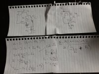
It kept me awake. By inspection:
Call the top of R4: Vx. Then Vx = R4/{R4 + (R3//[R5+Xc])}.
The feedback voltage is then: Vfb = [{Xc/(R5+Xc)} * (Vo-Vx)]+Vx.
Xc being the impedance of C2 and // means 'in parallel with'.
Now what?
Jan
jony how do you get there?? Can you do it step by step for dummies?
Jan
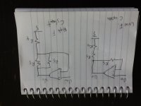
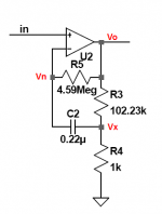
I use a "brute force" a Nodal analysis.

And wrote this forVn node.
(Vn - Vo)/R5 + (Vn - Vx)/(1/(s*C2)) = 0
And for Vx node.
Vx/R4 + (Vx - Vo)/R3 + (Vx - Vn)/(1/(s*C2)) = 0
And I solve for Vo I manage to find a transfer function.
AV = (1 + (C2 (R4 R5 + R3 (R4 + R5)) )/(R3 + R4) s)/(1 + (C2 R4 (R3 + R5) )/(R3 + R4) s)
Hence in the denominator of a transfer function, we have a single pole.
Fp = 1/( 2 * pi * C2* (R4 (R3 + R5) )/(R3 + R4) )
leadbelly,
the Sumerians insightfully implemented a sexegesimal number system long before the Babylonians. The French obsession of decimalizing time was clearly not an award winning approach. Mathematics had never been used in a more superstitious, religious, magical, paranormal, holy or weird way than it is in our time.
the Sumerians insightfully implemented a sexegesimal number system long before the Babylonians. The French obsession of decimalizing time was clearly not an award winning approach. Mathematics had never been used in a more superstitious, religious, magical, paranormal, holy or weird way than it is in our time.
Got in touch with Kendall but he feels it is an exercise for the reader. :cool
Now what?
Jan
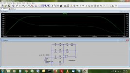
Now we look at the circuit at the freq extremes, where C is ( close to ) a short and an open.
At low f a gain of 1, at high f 1+ R5//R3 / R4 and since R5 is large 1+ R3/R4.
And I would GUESS the corner freq is at around Zc=R5 which is way up there. So a small cap will do. ( but Ild worry about parasitics at these high impedances?)
As the author says, its not HiFi.
Attachments
As the author says, its not HiFi.
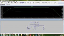
Why not? Increase the capacitor to 2.2 uF and the pole is at 1.6 Hz. I think the problem is the DC resistance in Mohm range which demands a FET input.
I can't imagine what you did wrong but op27 works fine for me. The DC resistance presented to both inputs is 100k in this example in order to cancel any DC offset. The op-amp is a surrogate for a power amp where 20K to 50K is typical.
In any case this is about AC response and impedance, not DC. If you are not familiar with circuit dynamics then "don't worry about it."
In any case this is about AC response and impedance, not DC. If you are not familiar with circuit dynamics then "don't worry about it."
Attachments
Last edited:
Why not? Increase the capacitor to 2.2 uF and the pole is at 1.6 Hz. I think the problem is the DC resistance in Mohm range which demands a FET input.
Even with fet inputs you might have trouble with offset. High resistance usually means high noise, and if the cap leakage resistance is in that mega ohm range you have to consider it. And somtimes with that high resistance other parasitics may effect things. Personaly i try to avoid extreme values, you have to start to consider stray inductance and capacitance as well as leakage, ESR, ect.
I can't imagine what you did wrong but op27 works fine for me. The DC resistance presented to both inputs is 100k in this example in order to cancel any DC offset. The op-amp is a surrogate for a power amp where 20K to 50K is typical.
In any case this is about AC response and impedance, not DC. If you are not familiar with circuit dynamics then "don't worry about it."
Sorry about that - the OP27 test was run on a single +15V supply whereas the LT1057 used +/-15V which makes a world of difference regardless with both op.amp results.
Even with fet inputs you might have trouble with offset. High resistance usually means high noise, and if the cap leakage resistance is in that mega ohm range you have to consider it.
The point with this arrangement is to reduce the capacitor value without having to increase the noise. Remember that the resistor in the megaohm-range is shunted by the capacitor. The problem could be the 1/f-noise, but with a proper value of the capacitor, this is not an issue in the audio frequency range.
And I think capacitor leakage is not an issue for most film types.
If we look at an audio amplifier as a subtractor amplifier it is quite simple to show that the noise ( and residual signal ) at DC blocking capacitor will reach output the same way input signal does ... this is wy this capacitor is so important ... and also layout of the circuit is critical around '' lifted ground ''
Attachments
- Status
- This old topic is closed. If you want to reopen this topic, contact a moderator using the "Report Post" button.
- Home
- Amplifiers
- Solid State
- Importance of the quality of the DC-blocking feedback capacitor?