I recently purchased a Marantz PM-66SE KI Signature (the same circuit as the PM-40SE, PM-44SE and PM-66SE, but with a toroidal transformer, a sprinkling of 'boutique' capacitors and a copper-plated chassis.
N.B. The PM-66* variants have an extra transformer winding for the remote control features.
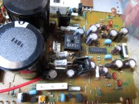
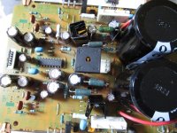
Whilst it appeared to be fully-functional (** I normally listen with the 'Source DIRECT' button engaged **), I was concerned by the amount of heat dissipated by Q801 & Q802.
I resolved to reduce the amount of heat dissipated by these transistors with the minimum amount of circuit modifications and parts.
I noted that R802 had been replaced. I also noted that Q801 was loose! Too much heat in a TO220 package.
Marantz_PM-66SE_KI_1_small.mp4
Marantz_PM-66SE_KI_2.mp4
N.B. I had a Marantz PM-44SE that used to intermittently drop-out the speaker relay, then re-engage a few seconds later. That amplifier 'disappeared' before I could investigate the cause (I now suspect Q801 as aove).
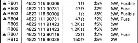
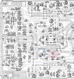
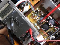
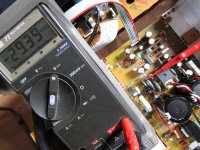
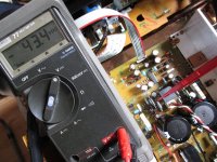
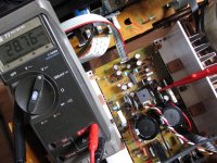
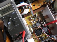
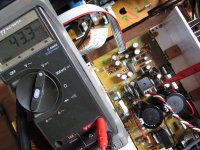
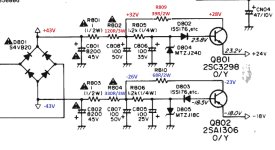
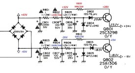
After measuring the voltage drops across R802 (47R / ~5V drop) and R804 (47R / ~3V drop), I determined that the +24V rail was supplying ~100mA (worst case - speaker + source direct relays engaged) and the -18V rails was supplying ~66mA (worst case - ALL LEDs illuminated).
It's not surprising that (according to 'the Internet') R802 is the most common failure with these amplifiers - it's severely underrated. It's a design oversight!.
R804, D804 & D805 also take a beating in the default configuration.
Marantz_PM-66SE_KI_PSU.jpg
Marantz_PM-66SE_KI_Resistor.jpg
** When I disengaged the 'Source Direct' relay, I lost the right channel (intermittently). Re-engaging the 'Source Direct' relay restored the right channel (always).
After replacing ALL the semiconductors and capacitors, the amplifier was completely destroyed.

The above sentence is completely untrue and is precisely what happens when you believe 'misinformation' on the Internet.
The right channel could be restored (temporarily) by moving the large ribbon cable (WV01), but would disappear minutes/hours later.
After chasing the intermittent problem, I discovered that the (never used) 'Balance' control had been 'whacked' by a previous (l)User.
Resoldering ALL the pins restored normal operation (but for how long?).
Balance_Control_Knob.jpg
N.B. The PM-66* variants have an extra transformer winding for the remote control features.
Whilst it appeared to be fully-functional (** I normally listen with the 'Source DIRECT' button engaged **), I was concerned by the amount of heat dissipated by Q801 & Q802.
I resolved to reduce the amount of heat dissipated by these transistors with the minimum amount of circuit modifications and parts.
I noted that R802 had been replaced. I also noted that Q801 was loose! Too much heat in a TO220 package.
Marantz_PM-66SE_KI_1_small.mp4
Marantz_PM-66SE_KI_2.mp4
N.B. I had a Marantz PM-44SE that used to intermittently drop-out the speaker relay, then re-engage a few seconds later. That amplifier 'disappeared' before I could investigate the cause (I now suspect Q801 as aove).
After measuring the voltage drops across R802 (47R / ~5V drop) and R804 (47R / ~3V drop), I determined that the +24V rail was supplying ~100mA (worst case - speaker + source direct relays engaged) and the -18V rails was supplying ~66mA (worst case - ALL LEDs illuminated).
It's not surprising that (according to 'the Internet') R802 is the most common failure with these amplifiers - it's severely underrated. It's a design oversight!.
R804, D804 & D805 also take a beating in the default configuration.
Marantz_PM-66SE_KI_PSU.jpg
Marantz_PM-66SE_KI_Resistor.jpg
** When I disengaged the 'Source Direct' relay, I lost the right channel (intermittently). Re-engaging the 'Source Direct' relay restored the right channel (always).
After replacing ALL the semiconductors and capacitors, the amplifier was completely destroyed.
The above sentence is completely untrue and is precisely what happens when you believe 'misinformation' on the Internet.
The right channel could be restored (temporarily) by moving the large ribbon cable (WV01), but would disappear minutes/hours later.
After chasing the intermittent problem, I discovered that the (never used) 'Balance' control had been 'whacked' by a previous (l)User.
Resoldering ALL the pins restored normal operation (but for how long?).
Balance_Control_Knob.jpg
Attachments

Iteration 1
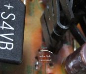
As I had a 5 pack of 150R/2W wirewound resistors, I replaced R804 with a 150R/2W wirewound and R802 with a 75R/4W (2 x 150R/2W in parallel) wirewound. I also removed the wire link adjacent to Q801 and installed a 75R/4W wirewound in R809 (which Marantz thought about, but didn't fit). This further reduces the strain on Q801.
Marantz_PM-66SE_KI_R809_link.jpg
Marantz_PM-66SE_KI_link.jpg
Heatsinks were attached to Q801 & Q802, power applied and measurements taken.
Although the transistors were cooler, I felt that further heat reductions could be made.
Marantz_PM-66SE_KI_Iteration_1_reduced.jpg
Iteration 2
Criteria: 5-10mA(max) through the Zeners/6-12V(max) across R805 & R806. Minimum heat dissipation in Q801 & Q802.
R802 120R/2W(min)
R804 330R/2W(min) (350R/3W preferred, but would be a 'boutique part)
R809 39R/2W
R810 68R/2W
Marantz_PM-66SE_KI_Iteration_2_reduced.jpg
R802_junction_R801.jpg
R802_junction_R805.jpg
Q801_Collector.jpg
R804_junction_R803.jpg
R804_junction_R806.jpg
Q802_Collector.jpg
Unfortunately, I didn't have a 330R/3W wirewound, so I used a 270R/2W wirewound.
Now that R802 & R804 are doing most of the 'heavy lifting', I can now keep my finger on Q801's heatsink!
C801, C802 and D801 were also replaced.
Parts were purchased from RS & Farnell.
Apart from the heatsinks, no audiophool 'boutique' parts were used.
Attachments
-
 Marantz_PM-66SE_KI_link.jpg244.9 KB · Views: 511
 -
 Marantz_PM-66SE_KI_R809_link.jpg354.8 KB · Views: 522
 -
 Marantz_PM-66SE_KI_Iteration_1_reduced.jpg138.2 KB · Views: 334
 -
 Q802_Collector.jpg150.9 KB · Views: 270
 -
 R804_junction_R806.jpg146.4 KB · Views: 251
 -
 R804_junction_R803.jpg145 KB · Views: 330
 -
 Q801_Collector.jpg147.4 KB · Views: 229
 -
 R802_junction_R805.jpg148.7 KB · Views: 235
 -
 R802_junction_R801.jpg144.4 KB · Views: 381
 -
 Marantz_PM-66SE_KI_Iteration_2_reduced.jpg134.6 KB · Views: 293
Attachments
Last edited:
You've obviously thought hard about the problems there but there are plenty more to consider before signing off on your efforts. The design looks a bit "pieced together" to my way of thinking and seems to have had more than one person at the drawing board.
For example, C801 and 802 are under-rated. The black triangle mark for those electrolytic caps has me puzzled too. Of course, that's only what is shown in your posts, there are likely more "errors" such as that. Also, If you are planning on ignoring the significance of the fusible resistors, don't forget that they are a necessary part of the design, so think carefully about safety when using the amp or leaving it unattended when powered. Read up on them and learn a little about designs that include fusibles where specified (that's the black triangles and "!" marks.)
For example, C801 and 802 are under-rated. The black triangle mark for those electrolytic caps has me puzzled too. Of course, that's only what is shown in your posts, there are likely more "errors" such as that. Also, If you are planning on ignoring the significance of the fusible resistors, don't forget that they are a necessary part of the design, so think carefully about safety when using the amp or leaving it unattended when powered. Read up on them and learn a little about designs that include fusibles where specified (that's the black triangles and "!" marks.)
Last edited:
I had a PM66SE as my main amp until just over a year ago when it died, dead, nothing, so probably a power supply issue like this.
I replaced it with a Cambridge Audio A5 and that was sonically, quite an improvement. I gave that A5 to a friend when I got my hands on some Linn kit dirt cheap and he is enjoying it to this day.
Point being, the PM-66SE isn't all that great sonically, yes, it's a good amp, but there are better ones that are common and cheap, so if yours is proving a PITA to get working, perhaps better to move it on and get something else.
The original power transformer likely had an internal thermal fuse. If it failed due to overheating or any other reason, the transformer would wind up just as useless as it would be if burnt out due to overload.
It's not clear in your posts, but according to the voltages shown on your schematic snips, you or the previous owner must have replaced the power transformer with one that has some 4VAC higher output. If so, this would certainly be the reason for an overheating problem and failure of the fusible resistors. Is the original schematic shown in the OP with only +/-38VDC main output correct for your model? Importantly, if you persist with the transformer's higher voltage supplies, it will necessitate a re-design rather than just patching over the problem with larger dropping resistors for the auxiliary 24 and 18VDC supplies. It should also be obvious that higher voltage rail voltages to the power amplifier won't be without their problems either. Check the capacitor voltage ratings there and whether fusible resistors there are still functional too.
If the transformer is incorrect, I can't see any problem with fitting a standard dual 25VAC toroidal in place of what appears to be a stock dual 30VAC type toroidal. (if that was changed, it would have been an ill-conceived "upgrade") Then you can get back to safe operation with raw 34V rail voltages and replacing the fusible resistors with appropriate similar, original spec parts.
The original power transformer likely had an internal thermal fuse.
.
.SNIP
.
If the transformer is incorrect, I can't see any problem with fitting a standard dual 25VAC toroidal in place of what appears to be a stock dual 30VAC type toroidal. (if that was changed, it would have been an ill-conceived "upgrade")
>9 months later... Apologies and corrections.
I may have previously posted circuit diagrams from a lesser model in the Marantz portfolio (probably a PM34, 40, 44 etc), which has lower secondary voltages. My apologies!


A 230/30-0-30 (+ an additional secondary winding for the uP) toroidal transformer is 'standard' in PM-66SE 'KI' models (as 'Modified in UK' by "a gang of villains in a shed up at Heathrow" - apologies to Squeeze) - it's original!.
According to the circuit diagram (widely available on the Internet), there is a thermal fuse fitted... I've not felt inclined to unwind the transformer and investigate further.
The default C801 & C802 are 12000uF/56V audiophool ELNAs, which were nicely 'domed' on the top (I believe that they have flat tops when they come off the production line).
They didn't smell bad, but the domed tops had me reaching for my hammer and chisel.
I replaced them with these 'bad boys'.
They have no audiophool pretensions whatsoever!

At £6.00 a piece, the amp sounds £12.00 better...!
In fact, after 9 months of 'burn-in', the amp sounds exactly like it sounded on the day the caps were replaced! Who knew?

Perhaps it's only audiophool caps that sound better after 100/200/(pick the latest audiophool random number) hours of 'burn-in'
I also replaced the bridge rectumfrier with something beefier.
The amp has been in daily use since I 'rationalised' the modification to 1 x 330R/3W wirewound resistor and 2 x wire links.
I can no longer hear Q801 and (to a lesser extent) Q802 screaming in pain from heat torture.

Power dissipation in Q801 has been reduced by >75%! That's a WIN!
View attachment 833326
View attachment 833328
View attachment 833327
Footnote: In the late 1980s/early 90s, Marantz UK were based (NOT in a shed) in Harmondsworth, just north of Heathrow airport, hence the Squeeze reference.
Last edited:
Hi Hamish,
You have done a great job in getting a better heat distribution, but the root problem still remains. This PSU circuitry should never have been placed in the middle of the pcb - close to electrolytic capacitors. And even with the new heat distribution it still fires about 3W into the surrounding components and pcb.
This is also why your big e-lytes were starting to dome.
It is a known problem that these TO-220 (or TO-126) can un-solder themselves - and that means that the leads have been over 180 oC - heaven only knows what the inside silicon die temperature has been!
Further, the pcb track laminate adhesive has probably started to brittle and weaken - and that is all that holds the trannies (now with additional heat sinks) to the pcb.
I would definitely chuck these trannies for a fresh pair. Drill a 2.5mm hole in each heat sink, tap it to M3 and mount the new PSU trannies on thermal pads where they can get rid of the heat. I sometimes use a ready made wire to connect the trannies to the pcb: 10Sets 3-Pin Mini Micro JST XH2.54mm Connector Plug Socket Wire Cable Cord 150mm | eBay
Then possibly re-trace some of the steps to let these trannies take back more of the heat again?
Oh, and you should also consider to replace the other e-lytes in the surrounding area, as they most probably also have dried out by now.
I did exactly this on a 66SE a few years ago and it worked a treat.
I can't remember now, but I think I actually did start to investigate whether the relays could be replaced by high-sensitive coil types (which reduces current consumption) and whether to replace the LEDs with superbright types (microamps instead of milliamps).
But, being the lazy b*gger that I am - most probably decided that it would be a solder joint too far.
Cheers,
Per
These are excellent suggestions, some of which I have considered - I have the electrolytic caps for the amp and transistors + regulators (cap multiplier + voltage regulation) for the RIAA amp. But, I don't use the RIAA amp and I'm the laziest B*stard on the planet (and a cheapskate)! It's too much effort......It is a known problem that these TO-220 (or TO-126) can un-solder themselves - and that means that the leads have been over 180 oC - heaven only knows what the inside silicon die temperature has been!
Further, the pcb track laminate adhesive has probably started to brittle and weaken - and that is all that holds the trannies (now with additional heat sinks) to the pcb.
I would definitely chuck these trannies for a fresh pair. Drill a 2.5mm hole in each heat sink, tap it to M3 and mount the new PSU trannies on thermal pads where they can get rid of the heat. I sometimes use a ready made wire to connect the trannies to the pcb: 10Sets 3-Pin Mini Micro JST XH2.54mm Connector Plug Socket Wire Cable Cord 150mm | eBay
Then possibly re-trace some of the steps to let these trannies take back more of the heat again?
Oh, and you should also consider to replace the other e-lytes in the surrounding area, as they most probably also have dried out by now...
Unlike you, e.g. when you make an 'improvement' and say to yourself "What if...?" and make further improvements (I've read Improve a Rotel amp THD by 20dB! - it makes me smile!), my 'What ifs...' usually end with a few beers and forgetting about the 'What if...' for a decade or two.

The reason I revisited this thread was that I was listening to a Technics SU-V303 which I'd been using in my workplace.
At home, it was immediately apparent (due to the lack of 'bass' and the olfactory assault) that the electrolytics were well past their 'best before' date (the caps should've been performing better than they did when new - they've had >10000 hours of 'burn-in').

Bizarrely, the SU-V303 reproduces music with 'air and spaciousness' (I dislike audiophool descriptions) which seem to elude the PM-66SE 'KI', which has audiophool pretensions (the same source and speakers were used...).
As they both use the AN7062 Voltage Amplifier (with slightly different implementations), this briefly led to a 'What if...' moment. Then I had a beer!

I may revisit this within the next decade.
I should clarify the above statement by stating the >75% heat reduction is under 'worst case' conditions: i.e. speaker relay plus 'source direct' relay energised.Power dissipation in Q801 has been reduced by >75%!
And, I also replaced R805 1k5/0.5W and R806 2k2/0.5W (it's what I had immediately available).
Q801 still requires a heatsink. 
Last edited:

- Status
- This old topic is closed. If you want to reopen this topic, contact a moderator using the "Report Post" button.
- Home
- Amplifiers
- Solid State
- MARANTZ PM-66SE KI Signature PSU Modifications