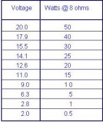
Warning DVM except for the $180 Fluke RMS version produce random numbers on AC volts scales on music. They are designed to measure power line frequencies. I use an analog VOM to measure AC voltages, which is why I quote Average voltages.
You can calibrate the scope with a zener diode driven by the AC signal through a power limiting resistors. Many AC sources like FM radio earphone jacks can put out 7 vac. Note a sine wave seen on a scope, Vav is 0.707 Vpp. RMS is close but more rigorous. Buy the zener from a ligitimate source like newark, mouser, digikey, RS. Put 1000 ohms over a 6 v zener on the line end, run a FM radio to the top of the resistor and the non-line end of the zener, turn radio all the way up, measure at the junction of the resistor & the zener. Scope should show a 6 v shelf from bottom of wave form (gnd is shaft of 1/8" phone plug) to the zener turn on point.
My point previous is that the circuit is designed to protect MJE21194 mounted on inadequate heat sinks, from excessive speaker current. With that heat sink & a stiff power supply, you can take off the limiters. Copy the experienced 7 transistor designers , Bigun TGM8 & John ellis basic 50. You don't need 21 transistors to make good sound, 6 is enough. If you're listening on speakers, those HD improvements in the 2nd & 3rd digit after the decimal point of the 21 transistors are for bragging, not listening IMHO. When you wire point to point as I do, the fewer the parts, the fewer wires you have to hook up.
Last edited:
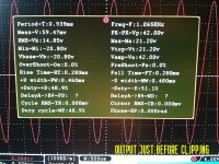
Ok, so I did some calibrating of the test equipment to insure accuracy, and here's some of my findings.
I'm a bit dissapointed at the output though, I thought I'd have more, it sure sounds that way hooked up to speakers.
So it appears that I'm only getting around 29 watts RMS/channel from this thing?
I'm a bit dissapointed at the output though, I thought I'd have more, it sure sounds that way hooked up to speakers.
So it appears that I'm only getting around 29 watts RMS/channel from this thing?
Attachments
Well the experts are somewhere else again. It's been 15 hours. Not much interest in speaker cap amps, people just love to burn up their speakers with split supply amps. They buy "speaker protector" boards that relies on a 15 A AC rated relay to disconnect the 1000 Adc fault current to their speaker. There is no zero volts to quench the arc through an AC rated relay trying to stop DC. Real relays used by Peavey are about $50 each. **** speaker protector boards have as many parts as this whole amp board.
What input voltage did you measure with the output just before clipping? As I asked in post 12, what voltages are at the collectors of tr504 (input transistor) and TR505 (VAS) when the clipping begins? Music, AC, not the DC voltages.
common emitter transistor gain is -Rc/Re so with 56:1 at tr504 and 50:1 at VAS tr505 the design might be doomed to clip. Besides the input transistor is running off 18v so there is no way you can get 25 vac out of it. The 2sc828 might be some *****y 25 vceo rated transistor that would overheat at 35 v supply, but that supply is what I am using for input transistor in my AX6 that puts out 70 W. If 80 v rated 2n5401/5551 or MPSA06/56 transistors are too expensive, try MPS8098/8099 which I got for $8 a hundred. I have my suspicions of the 2sc538 VAS, too. For VAS 120 v rated MJE15028/29 were on sale under $.50 each at newark two weeks ago. With MJL21194 outputs and a serious heat sink, you could also run the main supply up to 70 and go for 150 W peaks on the cannon shot of 1812 overture the way I am doing with my single output pair AX6. The 70 W I measured was over 5 loud seconds of a Rhianna song.
You're going to have to change some things to get better performance if your measurements are accurate. you'll have to pull R518 & R524 to increase the value and decrease the gain. I'm not sure that will do it, copying a TGM8 AX6 AX8 or John Ellis Basic 50 would be a surer path. I think there are some TGM8 boards out there on ali or ebay or something. There are patterns to make AX6 boards on the thread above but make a mask, etching and disposing of the waste chemicals are a PIT*. I found it easier to build AX6 on bare NEMA C board from mcmaster (they call it garolite) with 28 ga wirewrap wire & a soldering iron. The brown canvas reinforced stuff is 1000% easier to drill than glass reinforced board. Use a #46 drill, in a yankee hand crank drill if your electric drill chuck won't go that small.
Last edited:
14.5VRMS is a lot more power than than 8.4V peak would deliver if that had been the case. Let's say its near enough to 30 watts from +/- 25V rails which is not too shabby @ a nominal 4 ohm load with 89 db/W 1m sensitivity speakers. Yes, that would shake the room, like it does mine.Ok, so I did some calibrating of the test equipment to insure accuracy, and here's some of my findings.
I'm a bit dissapointed at the output though, I thought I'd have more, it sure sounds that way hooked up to speakers.
So it appears that I'm only getting around 29 watts RMS/channel from this thing?
To get a worthwhile volume increase on that already respectable level, you'd need a lot bigger amplifier with supply rails of at least +/-40V even with 4 ohm speakers. That's around 120W and I think you'd have to completely rebuild or simply replace the HK amplifier to get to the next level of house-shaker.
I've only seen the LSTs at shows and a couple of retailer demos many years ago. They were always out of my price and size range. Here's some facts and figures for anyone else reading: https://www.vintageshifi.com/repert...ge.php?pdf=Acoustic-Research-LST-Brochure.pdf
Last edited:
What input voltage did you measure with the output just before clipping? As I asked in post 12, what voltages are at the collectors of tr504 (input transistor) and TR505 (VAS) when the clipping begins?.....
Besides the input transistor is running off 18v so there is no way you can get 25 vac out of it.
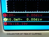
If you look at the photo that I posted for TR504, you'll see my mention of 16.15 volts RMS off collector at clipping. (listed as Vk on the screen)
My thinking is that since it's a capacitor-coupled output, I'm losing some "power" because of that coupling capacitor (4,700uF).
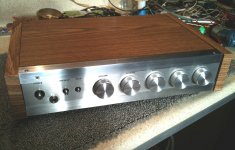
Otherwise, the amp sounds fantastic, clear, and dynamic.
If there's 1000A fault current to the speaker, the voice coil is vaporizing on a timescale of microseconds and a disconnect relay would be purely a spectator to the event! Speaker fault currents are limited by the resistance of the speaker coil to something much more managable, but is still DC at reasonably high voltages (most relays only have 24Vdc ratings for good reason, its hard to break DC and this difficult rises steeply with voltage).
A hard short will generate much higher currents (1kA is possible this way, but only for 10's or 100's of microseconds), but drain the filter caps rapidly and blow fuses. Shorts are likely to destroy output devices and would weld the relay contacts of even large relays if they reacted fast enough (which they can't - all the action is likely to be over before the relay moves).
Output device protection can prevent hard shorts leading to high currents in the first place - the combination of speaker protection and output device protection is indeed quite a lot of circuitry.
1kA is the sort of current that magnetizes nearby steel, and explodes thick copper wire. Oversizing filter caps is one way to risk this kind of damage!
14.5VRMS is a lot more power than than 8.4V peak would deliver if that had been the case. Let's say its near enough to 30 watts from +/- 25V rails which is not too shabby @ a nominal 4 ohm load with 89 db/W 1m sensitivity speakers. Yes, that would shake the room, like it does mine.
To get a worthwhile volume increase on that already respectable level, you'd need a lot bigger amplifier with supply rails of at least +/-40V even with 4 ohm speakers. That's around 120W and I think you'd have to completely rebuild or simply replace the HK amplifier to get to the next level of house-shaker.
I've only seen the LSTs at shows and a couple of retailer demos many years ago. They were always out of my price and size range. Here's some facts and figures for anyone else reading: https://www.vintageshifi.com/repert...ge.php?pdf=Acoustic-Research-LST-Brochure.pdf
Indeed, Ian, I originally built this amp to be used as a "Normal Listening Volume" type of amp, certainly not expecting to be a "powerhouse" with only a 52 volt supply.
I expected and so far have gotten a nice, clean-sounding, plenty of headroom amp with an indestructable output section and built-in speaker protection due to the capacitive-coupling design.
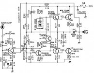
Not shown is an additional Zobel (R/L) network for stability, and speaker delay relay to the speakers to eliminate any "thump" at turn-on.
Going by my RMS wattage meter, during peaks of music, it hits about 50+ watts on occasion into 8 ohm speakers.
I'm getting 70w for 4 seconds out of a 3300 uf speaker cap. Nearly 24 vac on a simpson 260xlpm analog meter parallel a 8 ohm SP2-XT speaker. That was on bass notes of Shut Up & Drive. At 40 hz 3300 uf is 1.3 ohms impedance? 1/(2*pi*f*C) Less impedance at higher frequencies.My thinking is that since it's a capacitor-coupled output, I'm losing some "power" because of that coupling capacitor (4,700uF).
From a 3300 uf supply cap shared 2 channels. ST120 chassis does have a stiff 6.5 A 80 v transformer regulated to 70 v.
Mark T, the PV 1.3K has 10000 uf caps at 85 v connected through 10 ga wire to the output transistor board. It melted the lands to the crowbar triac off the board when the OT's shorted. Thick wide lands.
Last edited:
Looks great.
Less gain, more voltage headroom & rail current. You've spent the money on the output transistors & heat sink to deserve 70 w/ch. Hint, 400w switcher supplies like connexelectronic are more compact than a transformer, but require an inner steel box to keep the RF interferance down. May need a fan.
Less gain, more voltage headroom & rail current. You've spent the money on the output transistors & heat sink to deserve 70 w/ch. Hint, 400w switcher supplies like connexelectronic are more compact than a transformer, but require an inner steel box to keep the RF interferance down. May need a fan.
Last edited:
Cool build ")
As of:
As of:
follow my math, basically same as that from others, and you´ll be happy that you practically reached maximum possible ... you can´t go beyond rails or ground.I'm a bit dissapointed at the output though, I thought I'd have more, it sure sounds that way hooked up to speakers.
So it appears that I'm only getting around 29 watts RMS/channel from this thing?
Warning DVM except for the $180 Fluke RMS version produce random numbers on AC volts scales on music. They are designed to measure power line frequencies. I use an analog VOM to measure AC voltages, which is why I quote Average voltages.
You can calibrate the scope with a zener diode driven by the AC signal through a power limiting resistors. Many AC sources like FM radio earphone jacks can put out 7 vac. Note a sine wave seen on a scope, Vav is 0.707 Vpp. RMS is close but more rigorous. Buy the zener from a ligitimate source like newark, mouser, digikey, RS. Put 1000 ohms over a 6 v zener on the line end, run a FM radio to the top of the resistor and the non-line end of the zener, turn radio all the way up, measure at the junction of the resistor & the zener. Scope should show a 6 v shelf from bottom of wave form (gnd is shaft of 1/8" phone plug) to the zener turn on point.
My point previous is that the circuit is designed to protect MJE21194 mounted on inadequate heat sinks, from excessive speaker current. With that heat sink & a stiff power supply, you can take off the limiters. Copy the experienced 7 transistor designers , Bigun TGM8 & John ellis basic 50. You don't need 21 transistors to make good sound, 6 is enough. If you're listening on speakers, those HD improvements in the 2nd & 3rd digit after the decimal point of the 21 transistors are for bragging, not listening IMHO. When you wire point to point as I do, the fewer the parts, the fewer wires you have to hook up.
I think resistors R418 and R420 are a little big !!! For this reason, insufficient current is injected into the NTE 184 and 185 transistor bases and the output does not saturate to a higher peak-to-peak value. Normally, on the amplifier output before saturation you should record a ~36Vpp. Of course, those 36Vpp would be recorded if the PSU has adequate power.
So, a first step would be to slightly reduce the values of R418 and R420.
Looks great.
Less gain, more voltage headroom & rail current. You've spent the money on the output transistors & heat sink to deserve 70 w/ch. Hint, 400w switcher supplies like connexelectronic are more compact than a transformer, but require an inner steel box to keep the RF interferance down. May need a fan.
Thanks.
But I'm against using SMPS supplies with anything analog audio.
I much prefer "old school" linear power, much quieter, even if being bulky.
Well the experts are somewhere else again....
I dunno about them. My excuse is the forum ate my post. Quickly again....
You get 42V peak-peak from a "52V" supply. Assuming the supply sags 15% under full load, assuming a couple V loss each side, this is as good as it gets.
A 4700u cap won't lose much over the audio band. If you think it might, re-check the AC voltage at the other side of the cap. Probably about the same.
The circuit has worked well for 50 years. Fisher built tons of these. There was a Yamaha bass amp we had used nearly the same scheme.
Not using an output cap is elegant fashion and economics. If you build stereo, bipolar supply is two big caps, unipolar supply is three big caps. In one-off economics the extra cap is not a profit-buster; against that cost, cap-coupled amps often get-by without protection circuits which turn out to be "essential" in direct coupled amps.
I think resistors R418 and R420 are a little big !!! For this reason, insufficient current is injected into the NTE 184 and 185 transistor bases and the output does not saturate to a higher peak-to-peak value. Normally, on the amplifier output before saturation you should record a ~36Vpp. Of course, those 36Vpp would be recorded if the PSU has adequate power.
So, a first step would be to slightly reduce the values of R418 and R420.
I believe you're talking about R523/R525, if you're going by my revised schematic, (shown in later post) and the current design.
Thanks.
Cool build
As of:
follow my math, basically same as that from others, and you´ll be happy that you practically reached maximum possible ... you can´t go beyond rails or ground.
Indeed, thanks, I'm aware of the rail limitations and clipping factors.
As I mentioned, I primarily designed this to be used for "normal" listening with high quality, non-fatiguing sonics, and with an indestructable output section and hefty power supply.
So far, it's what I have, and should last decades.
- Status
- This old topic is closed. If you want to reopen this topic, contact a moderator using the "Report Post" button.
- Home
- Amplifiers
- Solid State
- Question about AMP modifications