Hi!
Good not needing to worry about the heatassociated discoloring.
CB45
Pin 1 0,49V (also labelled JDD)
Pin 2 0,49V (also labelled JDK)
So CB45 pin 1 is from IC44 pin 6, since the datasheet for UPC1237 says pin 6 is output pin of relay driver.
Tried to trace Pin 2 from CB45 and it is going to L21 and relay?
Is it the relay thats not switching? Or is it the UPC1237, read it closes the relay in order to prevent speaker disconnect shock. And the night I turned it off the last time, I though it sounded more agressive. Pin 3 is also stated to be the reset pin of the UPC1237, any ways to feed a reset signal and see if it works?
This is way more complicated, and interesting, but does it seem we can make her chooch again?
Thank you for spending time and effort in order to help me! Much appreciated!
Alright,we can proceed further to +/-18V section,as the relay is supply by +18V.Try measure each pin voltage of Q41 and Q43 respective to ground.
Hopefully the real issue is not the MCU on the front panel.
Last edited:
Alright,we can proceed further to +/-18V section,as the relay is supply by +18V.Try measure each pin voltage of Q41 and Q43 respective to ground.
Hopefully the real issue is not the MCU on the front panel.
Q41
E 0.64V
C 0V
B 0V
Q43
E 0V
C 39V
B 0.50V
This, seems a bit wierd in my eyes. Any clues?
Q41
E 0.64V
C 0V
B 0V
Q43
E 0V
C 39V
B 0.50V
This, seems a bit wierd in my eyes. Any clues?
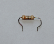
Try de-solder R45 and measure the ohms.
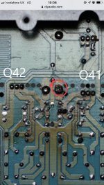
Images of the area to the front of UPC1237 and the left (towards transformer) of Q41 and Q42.
I don’t know much about the amp circuit but doesn’t one of those soldered connections show signs of deterioration, possibly overheating? Maybe worth a closer look.
Attachments
Try de-solder R45 and measure the ohms.
R45 desoldered
33,4 Ω, seems to be in spec (33R/0.5W 5% FS)
I don’t know much about the amp circuit but doesn’t one of those soldered connections show signs of deterioration, possibly overheating? Maybe worth a closer look.
Could I just heat it and resolder, or would any component check of use?
That and several other solder joints there just appear to have excess flux and solder. They've probably been re-soldered a little too much, to ensure they were good...... doesn’t one of those soldered connections show signs of deterioration, possibly overheating?....
That and several other solder joints there just appear to have excess flux and solder. They've probably been re-soldered a little too much, to ensure they were good.
Early (around 2006-07) the transformer was exchanged, through a servicecenter. Those days I was (very) young and had no real ambition to do DIY-repairs. If they de-soldered and re-soldered in the makes of fault finding or if it is factory - I do not know.
I've tried to measure different components throughout the mainboard, and the only thing that strikes me is that I can't really find any +/- 18V.
If any one has any suggestions where to continue the search for the bad component(s) I would be thrilled to measure, de-solder or swap parts.
Thank you!
R45 desoldered
33,4 Ω, seems to be in spec (33R/0.5W 5% FS)
Could I just heat it and resolder, or would any component check of use?
Now that's weird...if the resistor is ok,then the C pin of Q41 should have some voltages instead of zero.
Disconnect power and make sure all caps are discharged,measure the ohm from +18v to ground....u may get some low ohm reading initially (due to charging action the caps) but it will slowly rise up to higher ohm value.....If the ohm reading remain very low ohm all the time, then something is shorting the +18V rail.
If you haven't already referred to the service manual schematic, it's here: NAD C320BEE - Manual - Stereo Integrated Amplifier - HiFi Engine
On the main board schematic diagram, the +/-18V power supply is in the lower L/H corner.
The supply is derived from the main power rails of +/- 37VDC and regulator transistors Q41,42 (TO126 size power transistors 2SD669/649) are the regulator transistors and the rest of the circuit controls them. The input at the collectors should be about +/-37VDC and the output at the emitters should be about +/- 18N respectively for Q41/42. Simple as that. Assuming that is the case, you then trace where they lead by their reference points, according to the schematic.
If you don't find those voltages anywhere else (such as the protection board and ISC circuit), then the standby control circuit probably prevents them being activated and the amplifier wont start up. It's complicated yes, but that's why there are trained service people.
If you are tracing voltages, it's wise to secure the common probe to ground properly with a hook probe, clip lead or terminal and only use one probe with the other hand clear of the works - not only for personal safety but its all too easy to slip and take out many semis in a flash when juggling two probes as well as set and read the meter whilst checking voltages. Take care - you may only get one chance with either type of risk.
I was working on a 356bee i think. Read somewhere that the white filter caps should be replaces as they are of very poor quality.
Also found bad caps everywhere, specially close to the heatsinks for regulators.
Blown cap at power supply board for low voltage standby power also.
Also found bad caps everywhere, specially close to the heatsinks for regulators.
Blown cap at power supply board for low voltage standby power also.
Now that's weird...if the resistor is ok,then the C pin of Q41 should have some voltages instead of zero.
Disconnect power and make sure all caps are discharged,measure the ohm from +18v to ground....u may get some low ohm reading initially (due to charging action the caps) but it will slowly rise up to higher ohm value.....If the ohm reading remain very low ohm all the time, then something is shorting the +18V rail.
My bad. The solder joints of the Q42/Q41 have no good connection. When measuring on the pins, I get the readings below. Trying to trace. Q42 wiggles. But power seems to be feed downstream but activation of the PNP transistors to transform from 38V to 18V doesn't seem to work.
If you haven't already referred to the service manual schematic, it's here: NAD C320BEE - Manual - Stereo Integrated Amplifier - HiFi Engine
On the main board schematic diagram, the +/-18V power supply is in the lower L/H corner.
The supply is derived from the main power rails of +/- 37VDC and regulator transistors Q41,42 (TO126 size power transistors 2SD669/649) are the regulator transistors and the rest of the circuit controls them. The input at the collectors should be about +/-37VDC and the output at the emitters should be about +/- 18N respectively for Q41/42. Simple as that. Assuming that is the case, you then trace where they lead by their reference points, according to the schematic.
If you don't find those voltages anywhere else (such as the protection board and ISC circuit), then the standby control circuit probably prevents them being activated and the amplifier wont start up. It's complicated yes, but that's why there are trained service people.
If you are tracing voltages, it's wise to secure the common probe to ground properly with a hook probe, clip lead or terminal and only use one probe with the other hand clear of the works - not only for personal safety but its all too easy to slip and take out many semis in a flash when juggling two probes as well as set and read the meter whilst checking voltages. Take care - you may only get one chance with either type of risk.
Alas! Yes, we all start as beginners. I wouldn't have asked for help if I were trained or educated in this subject. But I see this as a perfect situation to learn more about the field, and I do not like to trow things on the ever increasing rubbish pile with out trying to do something about it. If it worked on the evening and not on the morning - I take my chances, maybe the surgery is flawless - despite the patient dying. It can't get more not working (okay, it may sustain worse and/or irreparable damages with me thinkering about - but I have no options). I have now started to understand more and more and with your encouragement I have tried to find +/- 18V on the board. It does not seem to exist, at all. And why, well that is what I was hoping for help in figuring out. I understand the basic components, and basic schematics for small insignificant curcuits. But this landscape of components working together needs a little extra help to navigate. And I thank you all for helping in this!
I started tracing from the standby on the supply circuit side.
-D403 4,6/4,02V
-- R401 4,02/0,64V
--- R49 0,64/0,42V
---- C47 0,42/0,5V (should be 18V)
--- Q43 (B) 0,64V
-- C45 0,64V/0V (culprit?)
--- Q41 (B) 0V. (not triggering the transistor? Switch "off"?) (PNP)
--- Q43 (C) 0V. (nothing on the collector.) (PNP).
---- R47 0V
On the transistors on the supply circuit
Q41
E = 0,5V
C = 38,7V
B = 0V
Q41 (E)
- C413 0,5/0,68V
- C47 0,5V
- D49 0,5/0,2V
...
- R428 0,5/0,35V
Q42
E = 0,5V
C = 38,7V
B = 0V
Q42 (E)
C414 + (-2,0V) - (-14,74V)
C48 + (-0,71V) - (-2,0V)
R412 -1,98/0,71V
C410 -2,0V/0,0V (GND)
C412 -2,0V/0,0V (GND)
Q43
C = 0V
B = 4,02V
E = 0V
Q44
C = -2,6V
B = 0,66V
E = 0V
C44
+ 0V (GND)
- -26,6V
C43
+ 19,84V
- 0V
R427 38,7V / 38,7V
- Q414 (E=0,16V;C=38,7V;B=0,34V)
- Q413 (B=0,00V;C=38,7V;E=0,34V)
Q413 B should be 12V?
R428 0,35/0,5V
R429 0,35/0,00V (GND)
R489 = 0,5/0,5V
Q411
E = 0,5V
C = -29,0V
B = 0,5V
FRONT PANEL CONNECTION
5V = 5V
12V = 0V.
ISC
D412 = 0,5/0,5V
R474 = 0,5/0,09V
R472 = 0,5/0,03V
IC43 pin 8 = 0,5V
Protection
R438 = 0,5V/0,0V
- D42 = 0,65V/0,0V)
Standby on the protection circuit
R437 = 4,6/1,12V
- D43 = 1,12/0.65V
It seems it all leads back to the Q41 and Q42 transistors. Why aren't they being feed, or are the simple not working?
I was working on a 356bee i think. Read somewhere that the white filter caps should be replaces as they are of very poor quality.
Also found bad caps everywhere, specially close to the heatsinks for regulators.
Blown cap at power supply board for low voltage standby power also.
Do you by any chance have the figure for the voltage of the standy power?
Tusen takk!
My bad. The solder joints of the Q42/Q41 have no good connection. When measuring on the pins, I get the readings below. Trying to trace. Q42 wiggles. But power seems to be feed downstream but activation of the PNP transistors to transform from 38V to 18V doesn't seem to work.
Alas! Yes, we all start as beginners. I wouldn't have asked for help if I were trained or educated in this subject. But I see this as a perfect situation to learn more about the field, and I do not like to trow things on the ever increasing rubbish pile with out trying to do something about it. If it worked on the evening and not on the morning - I take my chances, maybe the surgery is flawless - despite the patient dying. It can't get more not working (okay, it may sustain worse and/or irreparable damages with me thinkering about - but I have no options). I have now started to understand more and more and with your encouragement I have tried to find +/- 18V on the board. It does not seem to exist, at all. And why, well that is what I was hoping for help in figuring out. I understand the basic components, and basic schematics for small insignificant curcuits. But this landscape of components working together needs a little extra help to navigate. And I thank you all for helping in this!
I started tracing from the standby on the supply circuit side.
-D403 4,6/4,02V
-- R401 4,02/0,64V
--- R49 0,64/0,42V
---- C47 0,42/0,5V (should be 18V)
--- Q43 (B) 0,64V
-- C45 0,64V/0V (culprit?)
--- Q41 (B) 0V. (not triggering the transistor? Switch "off"?) (PNP)
--- Q43 (C) 0V. (nothing on the collector.) (PNP).
---- R47 0V
On the transistors on the supply circuit
Q41
E = 0,5V
C = 38,7V
B = 0V
Q41 (E)
- C413 0,5/0,68V
- C47 0,5V
- D49 0,5/0,2V
...
- R428 0,5/0,35V
Q42
E = 0,5V
C = 38,7V
B = 0V
Q42 (E)
C414 + (-2,0V) - (-14,74V)
C48 + (-0,71V) - (-2,0V)
R412 -1,98/0,71V
C410 -2,0V/0,0V (GND)
C412 -2,0V/0,0V (GND)
Q43
C = 0V
B = 4,02V
E = 0V
Q44
C = -2,6V
B = 0,66V
E = 0V
C44
+ 0V (GND)
- -26,6V
C43
+ 19,84V
- 0V
R427 38,7V / 38,7V
- Q414 (E=0,16V;C=38,7V;B=0,34V)
- Q413 (B=0,00V;C=38,7V;E=0,34V)
Q413 B should be 12V?
R428 0,35/0,5V
R429 0,35/0,00V (GND)
R489 = 0,5/0,5V
Q411
E = 0,5V
C = -29,0V
B = 0,5V
FRONT PANEL CONNECTION
5V = 5V
12V = 0V.
ISC
D412 = 0,5/0,5V
R474 = 0,5/0,09V
R472 = 0,5/0,03V
IC43 pin 8 = 0,5V
Protection
R438 = 0,5V/0,0V
- D42 = 0,65V/0,0V)
Standby on the protection circuit
R437 = 4,6/1,12V
- D43 = 1,12/0.65V
It seems it all leads back to the Q41 and Q42 transistors. Why aren't they being feed, or are the simple not working?
It's a simple scenario, the +/-18V supply rail being turn off, that's why you need to check if those rails are shorted to ground or not, which will put it into protection mode.
It's a simple scenario, the +/-18V supply rail being turn off, that's why you need to check if those rails are shorted to ground or not, which will put it into protection mode.
Thank you for sticking in there with me!
I've checked on the negative and positive rail, on the first and on some of the downstream component. Or should I check each one individual?
Supply circuit
Q41
E -> GND - 372Ω
R428 -> GND - 370Ω (on one side) and 1708Ω (on other)
Q43
C -> GND - 0 Ω
Q42
E -> GND - 4580Ω
C410 (+) 3,5Ω (towards GND)
C410 (-) 4560 Ω
C412 3,6Ω (towards GND) and 4560Ω
ISC
R427 (1370Ω/370Ω)
R469 (10390Ω/370Ω)
R468 (370Ω/54Ω)
Protection
R438 (56Ω/371Ω)
R440 (601Ω/370Ω)
Any ideas?
Do you by any chance have the figure for the voltage of the standy power?
Tusen takk!
No sorry. That amp would not power on at all and the cap was bulging bad!
Changed it and had power on, but a lot of other problems as well.
Thank you for sticking in there with me!
I've checked on the negative and positive rail, on the first and on some of the downstream component. Or should I check each one individual?
Supply circuit
Q41
E -> GND - 372Ω
R428 -> GND - 370Ω (on one side) and 1708Ω (on other)
Q43
C -> GND - 0 Ω
Q42
E -> GND - 4580Ω
C410 (+) 3,5Ω (towards GND)
C410 (-) 4560 Ω
C412 3,6Ω (towards GND) and 4560Ω
ISC
R427 (1370Ω/370Ω)
R469 (10390Ω/370Ω)
R468 (370Ω/54Ω)
Protection
R438 (56Ω/371Ω)
R440 (601Ω/370Ω)
Any ideas?
The negative rail incoming reading look fishy.
Anyway,I will draft some measurement reading you should take, in a picture format which will be more helpful than describing in words.
The negative rail incoming reading look fishy.
Anyway,I will draft some measurement reading you should take, in a picture format which will be more helpful than describing in words.
The effort you put in to help me diagnose the circuit is phenomenal. Your heart must be made out of pure kindness and gold. Thank you.
The effort you put in to help me diagnose the circuit is phenomenal. Your heart must be made out of pure kindness and gold. Thank you.
I read through your post and yes,we still need to stick positive rail.I do notice that the ohm reading is considerable low, which meaning there is something pulling the current.Since the +/-18V is supplying the preamp module too, can you remove all of them and measure the voltage again?And of course, those caps around the +18V rail might be the culprit too, but we can work on the module first.
- Status
- This old topic is closed. If you want to reopen this topic, contact a moderator using the "Report Post" button.
- Home
- Amplifiers
- Solid State
- NAD C320BEE - Bad capacitors?