I am interested. If you can get it into 100mm by 100mm (outputs on both sides) then some board houses would be $2 special plus shipping.
80x200 is posssibile
But I dont know its worth to spend time for A40 for same size you can get 1500 W Class D @ 4 OHM
Last edited:
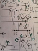
It looks like a lot of the working A40's I've seen are using Alex's (very nice) Rev 1.4 board, is there an updated schematic to go with that?
It seems like the boards get revised but not the schematics.
There is also a rev 1.6 board, HatlessChimp did you build using that? What is the signal ground to power ground via the diodes/resistor for?
It seems like the boards get revised but not the schematics.
There is also a rev 1.6 board, HatlessChimp did you build using that? What is the signal ground to power ground via the diodes/resistor for?
a40 possible mistake
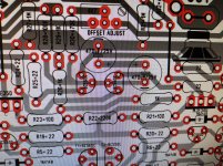
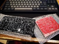
Hi, Im testing a40 right now, it works very good but it has slight broom with or without something connected to input (probably something about wiring). Anyway, in search of a cause of that broom I noticed that on Alexmm's 1.4 board elco with value of 220uF has been replaced with 2 elcos of 470uF in series, but on silcscreen it seems one of them is inverted. I changed orientation of one elco in hope it will soove broom but nothing changed") . Amplifier works same as before the change. Should I leave elco like that or is it really a mistake on board ver. 1.4?
. Amplifier works same as before the change. Should I leave elco like that or is it really a mistake on board ver. 1.4?
Edit: Or maybe those 2 elcos are in function of one bipolar elco?
Hi, Im testing a40 right now, it works very good but it has slight broom with or without something connected to input (probably something about wiring). Anyway, in search of a cause of that broom I noticed that on Alexmm's 1.4 board elco with value of 220uF has been replaced with 2 elcos of 470uF in series, but on silcscreen it seems one of them is inverted. I changed orientation of one elco in hope it will soove broom but nothing changed
. Amplifier works same as before the change. Should I leave elco like that or is it really a mistake on board ver. 1.4?Edit: Or maybe those 2 elcos are in function of one bipolar elco?
Attachments
Last edited:
UNCONFIRMED A40 FILES
These files I am unsure if they are usable. Would be nice if someone could please help me verify them and provide some information on them. Thanks!
Hi!
would you drop asc file for LTSpice playing?
thank you in advance!
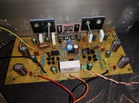
Hi Guys.
Im going to build a amp. As A40 is one of the most documented builds ill try to build it. I did a headphone amp before so i,ve little experience.
First step is to get the pcbs. I'll order them in PCBway but i have some doubts.
Minimal holes size, 2mm, 2oz copper etc is it worth it? attached is the order screen and the fields. Could you be son kind and help me.
I'm going to buy too pcbs for the ax-14 as is one of the easier to build and Apex recommend to build it. Which psu can i use?
Thanks in advance.
Attachments
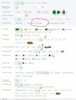
Hole size should be determined by the drill file within the gerbers zip file, so you should need to change it.
IMO you don’t need to go with 2oz copper, many have built with the standard amount, but it’s DIY so get what makes you happy/comfortable/afford.
I have run the AX-14 with three PSUs and two voltages without a problem- cheap 500w SMPS from China at +\-55Vdc, and two toroidal/rectifier supplies at +\-63Vdc and +\-53Vdc and couldn’t tell any difference. I optd to use the lower voltage and play it safer at lower ohm loads. Should be safe up to 65-70Vdc on the A40, but stay <55Vdc on AX-14 and you should have years of trouble-free listening.
Suggestion - look at the SR200 from APEX, similar to A40, fewer transistors and I believe APEX was asked directly his preference and he said the SR200. Either are a great choice though.
renew q
Hi!
would somebody drop asc LT Spice of A40?
thank you in advance!
Hi!
would you drop asc file for LTSpice playing?
thank you in advance!
Hi!
would somebody drop asc LT Spice of A40?
thank you in advance!
Somebody can suggest me a PSU for this amplifier?
I'll appreciate Gerber files...
Thank you so much...
Did you get any suggestion? I´m looking for a PSU too and a speaker protection for this amplifier.
Thanks
Hi!
would somebody drop asc LT Spice of A40?
thank you in advance!
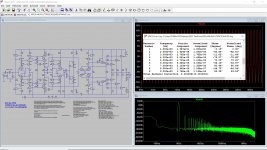
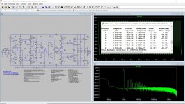
I have attached my first cut LTSPICE simulation for A40.
For "view > FFT" use Blackman-Harris window and Vout.
Attachments
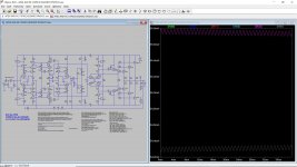
Maybe. I did a quick simulation (attached) and it looks promising. But I would suggest asking the APEX A40 designer about possible parts swaps and upgrades. And run gain/phase to look at stability.
I wonder about TTC004B/TTA004B and 2SC5171/2SA1930 (I have 7 pairs used/genuine from a receiver).
I also wonder about 2SC5200N/2SA1943N outputs. Those lowered distortion (actual measured distortion) in one amplifier I tried. Possibly the lower capacitance?
I wonder about TTC004B/TTA004B and 2SC5171/2SA1930 (I have 7 pairs used/genuine from a receiver).
I also wonder about 2SC5200N/2SA1943N outputs. Those lowered distortion (actual measured distortion) in one amplifier I tried. Possibly the lower capacitance?
Attachments
Last edited:
- Home
- Amplifiers
- Solid State
- Apex A40 Amplifier Build Thread