Hello,
I have a Sansui 6060 that was my dad's growing up. It's an amp that we've used for a lot over the years and love it (both for the sound and the memories).
However, recently I have some problems with it. What it does is this: when I push the power button and turn it on instead of hearing a "click" shortly after the power button is engaged and the sound turns on, instead I hear nothing and the sound does not turn on. Occasionally after waiting a little bit I hear the "click" (which I assume is a relay) and then the sound works fine. But increasingly I do not hear the "click" and there is no sound.
Any one ever run into this? Any ideas on how to diagnose and fix?
I've done a fair amount with guitar tube amps, but never with receivers which seem a fair amount more complicated.
Any help would be very much appreciated. I have VOM and Oscope if needed.
Thank you!
Daniel
Thanks nigelwright7557.
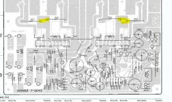
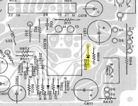
I looked over the schematic and did my best to locate the bias circuit and relay (sorry for ignorance if I'm not looking at the right area). See attached. Would I just check to make sure each of the spots located in the attached schematic have the same voltage. If so, what should that voltage be? The capacitor says 50V; but the orange highlighted portion on the schematic (which is very hard to read) I believe says 37V. I assume I should check to make sure both are at 37V. If not then replace C519 and C520?
Do you think I should replace the Relay as well?
Thanks again.
Attachments
Any electrolytic cap in something of that vintage(*) is suspect. The amp should really have a recap, otherwise a whole slew of issues will be cropping up in the next decade or two. To start with the protection circuit should be recapped (its important it does its job properly), and then the power amps (which are likely to have run hotest). Also worth carefully removing any dust and grime build-up.
(*) 40 years or so according to a quick search.
(*) 40 years or so according to a quick search.
Two probable scenarios.
Fault in power amp stage resulting in excessive Vdc being placed on the speaker line.
Protection circuit doing its job of not activating the relay thereby protect the spkrs.
Fault in protection circuit, it doesn't activate the relay after the mute period.
For power amp issue, measure dc voltages between emitter resistors to ground/chassis
to identify problematic channel
Attachments
The circuit still works but the relay drive timing caps have most likely dried out and become unreliable, as nigel pointed out. Specifically, the small timing electrolytic associated with start-up delay is likely dying but so will most other electrolytic caps in there, after 40+ years.
You could try replacing just C601, C602 (preferably with ≥ 16V types) but really, after 40+years, the whole lot of electrolytic capacitors will need replacing. If you can't identify what electrolytic caps look like, it might be wise to enlist professional help. Audio repairers are fully familiar with the need and are usually pretty quick at this.
You could try replacing just C601, C602 (preferably with ≥ 16V types) but really, after 40+years, the whole lot of electrolytic capacitors will need replacing. If you can't identify what electrolytic caps look like, it might be wise to enlist professional help. Audio repairers are fully familiar with the need and are usually pretty quick at this.
mbz - I checked the voltage between the emitter resistors; both locations were 35.7V DC to ground. What do you think? That look ok? … what should I check next?
Ian Finch - thanks for the input. It does seem like if there are caps responsible for the relay opening, they would be suspect. Replacing a couple caps shouldn't be a problem. I was looking and can see where 601 and 602 are in the layout but can't find them in the schematic. Am I missing them?
Regarding having a tech do a full cap replacement... what do you think something like that would cost? It looks like there has to be 40 or 50 electrolytic caps in this thing.
Thanks!
Daniel
Another data point...
The manual has a procedure for adjusting the bias current. I attached a copy for reference.
I made some measurements:
1. Step 1 - at R05 and R07 - I measured 33mV initially and it slowly climbed and seem to somewhat stabilize at 39mV (although it seemed like it kept climbing).
2. Step 2 - at R06 and R08 - I measured 49mV initially and it slowly climbed to about 54 mV and somewhat stabilized (although it seemed like it kept climbing).
It seems weird that the DC voltage kept climbing. Is that normal?
The procedure calls for these to be adjusted to 15mV +/- 1mV. Since the value I measured is quite a bit higher... seems like maybe this is the culprit? Looks like I can adjust VR01 and VR02 to reduce. Maybe that will fix it? I would love to get some input before I proceed further and start changing things.
Attachments
mbz - I checked the voltage between the emitter resistors; both locations were 35.7V DC to ground. What do you think? That look ok? … what should I check next?
Daniel
If you measured correctly then that would not be good.
There will be some transients immediately at power on and for a few 3-5
seconds after that. The emitter resistors are typically large (1inch x 1inch).
You would be unlucky to have failures on both channels, typically such
voltages would be caused by shorted output transistors, eg, c-e short.
Suggest recheck your measurement, maybe measure at the relay itself,
then consider diode testing output transistors (amp powered off/unplugged)
Attached is a scan that shows where I tested and the values.
I measured 35.7V at the intersection of R08/R06 and at the intersection of R07/R05. I used the transistor heat sink / housing to ground to. Is that ok? If 35.7V is too high... what value should that be? Both channels work fine and the receiver sounds great when/if the relay engages. So I'm guessing maybe if the voltage is way off I measured wrong?
Regarding the bias current measurements. I highlighted the measurements I took. As shown in the attached sketch both 49mV and 39mV is way out of spec. It looks like I can adjust it to spec (hopefully) using VR01 and VR02. Should I do that and see if it fixes things? It seems to me since this is way out of spec and directly tied to the relay it is definitely highly suspect?
Also Ian Finch suggested replacing C601 and C602. I can do that, and found them in the schematic (see attached schematic excerpt 2)... but want to confirm those are the capacitors that are responsible for timing on opening the relay? I'm having trouble understanding from the diagram how these relate to relay opening timing. I'm not super savvy at reading diagrams so will trust your input... but want to confirm.
Thanks again everyone!
Attachments
Just to be certain that every cap on the protection board is in good order, you could also replace the others on that PCB. They are associated with various power supplies and will all have to be replaced eventually. I can't read all the relevant numbers of the caps from the schematic but you have the PCB and components to refer directly, so just go through and list all of them systematically, then when you replace them all, you'll know that the board is OK for another 40 years and you don't have to go back and pick up the threads of what you did or didn't do earlier.
Note that modern caps are a lot smaller and you may not get the old axial style at all in some values, if they are needed. (that's where the leads are in line with the axis of the cap's body) . I suggest not fitting caps of less than 16V rating either, just for reliability.
Note that modern caps are a lot smaller and you may not get the old axial style at all in some values, if they are needed. (that's where the leads are in line with the axis of the cap's body) . I suggest not fitting caps of less than 16V rating either, just for reliability.
Attached is a scan that shows where I tested and the values.
I measured 35.7V at the intersection of R08/R06 and at the intersection of R07/R05. I used the transistor heat sink / housing to ground to. Is that ok? If 35.7V is too high... what value should that be? Both channels work fine and the receiver sounds great when/if the relay engages. So I'm guessing maybe if the voltage is way off I measured wrong?
Can you redo the measurement with the black meter probe connected to any
black speaker post. Looking for less than +/-10mV in a perfect world. Less than
+/-20mV is great and less than +/-50mV is tolerable. +35Vdc would certainly
exercise the protection circuit.
Hi,
Suggestion if you check the voltage at the positive side of capacitor c601 that it is connected to the base of the transistor TR631??? if it is reading 0 the relay should be enable and a positive voltage will disable the enabling of the output relay. The input it is coming from the speaker output.
Suggestion if you check the voltage at the positive side of capacitor c601 that it is connected to the base of the transistor TR631??? if it is reading 0 the relay should be enable and a positive voltage will disable the enabling of the output relay. The input it is coming from the speaker output.
Can you redo the measurement with the black meter probe connected to any
black speaker post. Looking for less than +/-10mV in a perfect world. Less than
+/-20mV is great and less than +/-50mV is tolerable. +35Vdc would certainly
exercise the protection circuit.
I re-measured DC from the R08/R06 connection to the ground pole on the back of the amp (instead of putting the ground on the transistor housing) and now come up with 0.030V for R05/R07 and 0.040V for RO8/R06. Much less than the 35V was measuring before. Note the voltage was higher (above 0.05V before I when I first turned it on then slowly dropped to those values).
OK, so what you've got is a delayed relay click. The delay could
be cuased by excessive dc voltage/transients after power up or
a fault in the protection circuit possibly faulty "timing" of the
mute period.
Would be helpful that you monitor the dc voltage after power up a few
times. Previous post mentions 0.05Vdc, if that's as bad as it gets then
it's not the issue, expect to see 0.6->maybe a few? 3-10?V
C602 (330/6.3V) is the main cap for mute timing, consider replacing it.
ZD601 is also a candidate.
Try to get the following voltage measurements after the mute period but
before the relay click, ie, relay click is delayed by fault.
measure TR603 base and ZD604 anode then cathode to ground (black spkr post).
TR601b and TR602b also to GND may be useful. Wait about 5 seconds then
perform the measurements before the relay click.
OK, so what you've got is a delayed relay click. The delay could
be cuased by excessive dc voltage/transients after power up or
a fault in the protection circuit possibly faulty "timing" of the
mute period.
Would be helpful that you monitor the dc voltage after power up a few
times. Previous post mentions 0.05Vdc, if that's as bad as it gets then
it's not the issue, expect to see 0.6->maybe a few? 3-10?V
C602 (330/6.3V) is the main cap for mute timing, consider replacing it.
ZD601 is also a candidate.
Try to get the following voltage measurements after the mute period but
before the relay click, ie, relay click is delayed by fault.
measure TR603 base and ZD604 anode then cathode to ground (black spkr post).
TR601b and TR602b also to GND may be useful. Wait about 5 seconds then
perform the measurements before the relay click.
Sorry for the delay. I was tied up with some family stuff. Now back on this.
I'm having trouble finding ZD604. I can find ZD601, ZD602, and ZD603... but can't find ZD604. Is it on a different board?
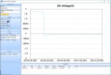
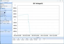
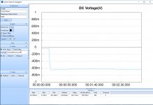
I ran some voltage measurements using my Silgent 3088 and EasyDMM on TR601B, TR602B and TR603B. Attached are screenshots of the outputs. Note, for some reason now the relay seems to be opening about 1 to 2 seconds after I turn it on. I'm not sure if just sitting unused for a few weeks has changed something but the relay is not delaying like it was. I'm not getting my hopes up... and I'm sure this is short lived... but keep that in mind when you look at the graphs of the voltages at TR601B, TR602B, TR603B.
Note the boxes below the graph give the voltage statistics. The "Data" box is the final voltage (IE where it stabilized at).
What do you think?
Attachments
Regarding ZD604, it's the diode across the relay coil, see schematic.
It's marked as ZD603 on the silkscreen, see pic.
I'm unsure of the time scale on the graphs supplied. eg, TR601B appears to show a "step"
voltage lasting 20 seconds. Such a voltage would explain the delay relay activation but
you are saying the relay is operating after 1-2 seconds which I would think is too
quick ie, the timing cap is charing up too quick, suggest replacing C602 330uf/6.3V
with 330uf/16or 25 or...V
Attachments
- Status
- This old topic is closed. If you want to reopen this topic, contact a moderator using the "Report Post" button.
- Home
- Amplifiers
- Solid State
- Sansui 6060 - power on issue