X,
Interesting. So are you saying the DUT should have a low noise supply or the Focusrite unit or both?
Best,
Anand.
The Focusrite power supply is internal and powered via its usb so nothing to do there except having a pc with a low noise motherboard.
For the DUT, the measurements shows you a combination of the performance of the PSU and the amp. For the above amp, it’s a SE Class A design with a CCS but having a clean PSU is important.
Interesting stuff, great initiative!
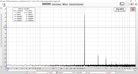
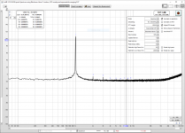
So I installed REW followed the instructions and came up with the attached plot. This is using the internal signal generator.
I found the results greatly depends on the input amplifier and output settings. Which is probably quite logic (less gain less distortion, and also less noise). The input gain of my Focusrite 2i2 is set at min while the output is at max.
One question: when I click the camera icon in the top left I'm able to save the current plot. But that doesn't show the distortion panel. Is here a setting somewhere I need to modify? (the attached picture is a screenshot generated by the prtscrn button).
Attachments
There is a checkbox when you save the image of the screenshot to show distortion panel. It works. The only thing that doesn’t show is the settings panel - which is useful for showing what the averaging is, number of points, window used, etc. for that you need screen capture of window with print screen button.
Your result looks very good.
Your result looks very good.
I am cranked to get started
Got several”projects” I want to test. Need to reread this. Played with REW a little, just updated the software. If it can measure a noise floor at -150 dB it will work for my use.
Purchased the 2 ppm 1 kHz generator kit. Need to build it. Want to start with internal signal generator, like to see noise floor fall when changing from 16 bit to 24 bit signal. Good indicator of interface resolution.
Will use a Focusrite Clarett. But the cheap models test excellent. Not sure an expensive one can be deliver better measurements.
The noise floor depends on your audio interface - the Focusrite Solo/2i2/2i4 seems to have circa -125dB to -135dB noise floor. Depends on input gain and noise of your PC’s USB power supply too. I noticed newer laptops with SSD are quieter and can make measurements plugged into wall power even.
Thru the floor - I hope
I use an optical Thunderbolt cable for galvanic isolation, a galvanic isolated iFi iPower supply for Clarett, and some magic in the interface and computer.
Hope to see better than normal noise floor. But will not know until tested.
There is one test I want to run, tricked out interface and a completely out of the box unit with stock supply and Apple TB cable to see if the changes make a measurable difference.
The noise floor depends on your audio interface - the Focusrite Solo/2i2/2i4 seems to have circa -125dB to -135dB noise floor. Depends on input gain and noise of your PC’s USB power supply too. I noticed newer laptops with SSD are quieter and can make measurements plugged into wall power even.
I use an optical Thunderbolt cable for galvanic isolation, a galvanic isolated iFi iPower supply for Clarett, and some magic in the interface and computer.
Hope to see better than normal noise floor. But will not know until tested.
There is one test I want to run, tricked out interface and a completely out of the box unit with stock supply and Apple TB cable to see if the changes make a measurable difference.
You realize noise-floor is given by a power-spectral-density plot, not a power spectrum plot?
You have to correct for noise bandwidth, number of FFT bins and the window function shape to convert between the two.
If you don't do this you'll see your noise floor level changes with different FFT sizes and sampling rates and changing window functions, rather than being a measurement of anything real!
Not sure many people understand these points. Here's a great paper that goes into full detail on the subtleties of spectral measurement using the FFT: http://holometer.fnal.gov/GH_FFT.pdf
Thanks X for the excellent how-to!
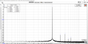
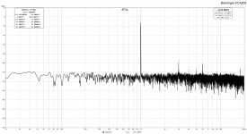
I had to purchase me a brand new Focusrite Scarlet 2i2 and attached is my loopback measurement result with -3dBFS digital level and 2,08Vrms analog level using balanced in/out connections and REW signal generator.
I think I’m good now to proceed to amp measurements too...")
I had to purchase me a brand new Focusrite Scarlet 2i2 and attached is my loopback measurement result with -3dBFS digital level and 2,08Vrms analog level using balanced in/out connections and REW signal generator.
I think I’m good now to proceed to amp measurements too...
Attachments
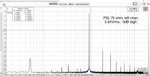
...and here is the measurement of my Pioneer Super Linear headphone amp @70 ohm load on the left channel and pushing 100mW of power (2,64Vrms). The digital level of the REW signal gen was -3 dB.
The results seem to be reasonable and it is nice to have this kind of sanity check for the build.
The results seem to be reasonable and it is nice to have this kind of sanity check for the build.
Attachments
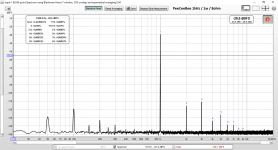
Okay, so I measured one channel of the PeeCeeBee V4H amplifier. This is with the amplifier running with an output voltage of 2,83 volts into 8 ohms (dummy load). I used REW as the signal generator.
The plot is attached. The author has far better measurements, so maybe I'm doing something wrong?
The plot is attached. The author has far better measurements, so maybe I'm doing something wrong?
Attachments
Last edited:
ESI Juli@
X, thanks for the great guide.
Attached are my results for an internal PCI ESI Juli@ loopback. On your recommendation, I built an Akitika 2ppm oscillator. What an easy and simple kit!
My entire setup is:
- Akitika ->
- jan.didden's Linear Audio Autoranger (The L|A Autoranger | Linear Audio NL, Autoranger for soundcards) for attenuation ->
- TRS balanced output ->
- ESI Juli@'s (ESI - Product Archive: Juli@) balanced input
Overall I'm a happy camper and think this will fit my needs just fine. I was using ARTA before, but think I'll now explore REW a bit more.
Greg
Edit: Noise seems a bit high... I'll need to dig into that, maybe because its a noisy desktop PC next to my AC unit?
Attachments
Last edited:
Issue with Apple
I have Mojave installed on my Mac Mini. Could not get a signal on loop back.
Played with every setting and did not get it going. Finally went to Focusrite and saw something about allowing “Microphone” to receive signal back.
Went to permissions and there it was. Gave permission, and bang I had a RTA.
Noise was down around -140 dBSF. But even with REW generator at 0 dB, the 1 kHz Pulse is around -128 dB. Dropping output of generator drops the spike at 1 kHz.
I have clicked a lot of buttons in Focusrite control and in REW when Mojave was not accepting the input.
Changed the output to volts and set it at 1 volt. Still just a little spike.
Cannot see where the signal is being attenuated. I am sure it is something simple that I have done.
Anyone more familiar with the system know why a 0 dB signal and a 1 volt level both generate a pulse at 1 kHz that rises 12 dB or so above the noise baseline?
- Home
- Design & Build
- Software Tools
- How to - Distortion Measurements with REW