Hi All,
Fairly new here 😁 thought I'd share here some of my story repairing and restoring a "parts" HA-4700 from TradeMe. If anyone's interested.
When I got it, the lights were on but there was no output at all.
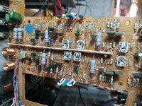
What I found was one channel with the output emitters sitting around 8v, the other at the + rail more or less. Dead output on that one I thought. But it turned out that every single 1/4w "fusible" resistor in the thing was either high Z or open. This was the same problem as was found in the excellent YouTube video by JoulesperCoulomb which was what prompted me to start checking them.
Replacing them all with standard metal film resistors ("fusible" resistors in those values proved hard to come by and normal metal film resistors should work well enough at failing open if need be) brought it to life except for a several megahertz oscillation (another problem also found in the video! These must be reasonably common issues) which was due to some of the (weird) axial caps gone bad. Replaced those with mlcc type and that sorted it! Adjusted the bias and DC offset and was away. A few dry joints fixed along the way and of course new thermal paste for the power trannies.
Knowing it was serviceable, I moved onto cosmetics, restoration and tidy up. So far
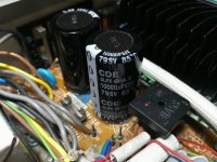
* Replaced 8200uF bulk caps with 10000uF CDE caps. They actually tested fine at over 7000uF apiece but 8200 seemed kind of small for a 50W amp anyway.
* Replaced dead "TAPE" bulb with yellow LED
* Replaced incorrect 1N4004 diodes on indicator/selector board with the correct 10v zener
* Removed case bottom for corrosion and paint repair
Still to do:
* Replace other indicators with LED
* replace a switch I broke 😭 which is going to be tricky
* polish up the chromed buttons and knobs best I can, they're a bit corroded (green spots)
* Clean up rust on case and repaint
* Clean up rust on transformers and paint
* Receive new volume knob (was missing)
* Reassemble!
If people are interested I have loads of photos so... Let me know if you wanna see them.
Here's some pics of the state I got it in... Fairly rough:
"Parts" Hitachi HA-4700 Original State - Google Photos
Is the thing working in its original state, after replacement of faulty parts?
Yes it is working after replacing just the 1/4w resistors and a couple of capacitors (the Miller caps near the inputs of the output stage) and touching up a few dry solder joints. I suspect there is a tendency in these to build up heat between the heatsinks in the output amp stage, especially if something else is sat on top, the case has a very low profile and there aren't many other places for the heat to escape. This unit was assembled here in NZ, at least partially, this will be due to tough import levies in place at the time.
I work repairing inductrial equipment here in Argentina, and it is very common problem the solder joints fatigued and broken, with intermitent contact.
The question arises because I was to suggest that previously to start modding, was better to put it working as is, and once the thing jobs OK, then start modding. In any case, try one at time, so it is easily to go back if something goes wrong.
The question arises because I was to suggest that previously to start modding, was better to put it working as is, and once the thing jobs OK, then start modding. In any case, try one at time, so it is easily to go back if something goes wrong.
Exactly my approach [emoji6]I work repairing inductrial equipment here in Argentina, and it is very common problem the solder joints fatigued and broken, with intermitent contact.
The question arises because I was to suggest that previously to start modding, was better to put it working as is, and once the thing jobs OK, then start modding. In any case, try one at time, so it is easily to go back if something goes wrong.
Here it is working after the minimum repairs, playing some DSOTM at "hi neighbour" levels in my garage [emoji16]
Shared album - Dan Capper - Google Photos
Shared album - Dan Capper - Google Photos
Did some rust stripping tonight... Must have been dripped on [emoji51] there's even a hole. I've worked on cars with less rust [emoji38]
Shared album - Dan Capper - Google Photos
Shared album - Dan Capper - Google Photos
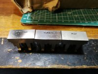
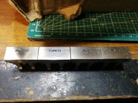
Between much difficulty in replacing the switch and trying to figure the best way to tackle the very rusted out top cover, I decided I would polish the buttons. First some ultra fine steel wool to take off the corrosion spots, then a car polish, then turtle wax scratch and swirl remover which is a fine polish and wax finish. Turned out not bad. Still need to do the smaller ones and tone controls when I get time, but should be easy.


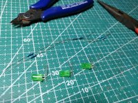
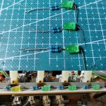
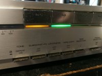
Today, as I wait for new switches since the small ones I ordered aren't going to work, I replaced the remainder of the input selection indicators with LEDs. Turned out fairly neat I think. I also gave the front panel a light polish and wax. Looks like one side of the plastic trim needs retrobrite, I may attempt it tomorrow if the weather stays good and I can find what I need.


Since most of the other photos are just Google links I'll post them a few here for completeness...
1. Small buttons mostly polished
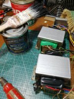
2. Transformers stripped and painted
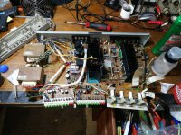
3. Whole unit after changing the bulk caps
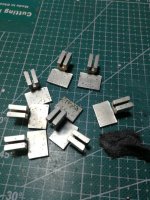
4. Old busted fusible resistors in the power amp
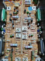
5. One channel with new resistors installed
1. Small buttons mostly polished
2. Transformers stripped and painted
3. Whole unit after changing the bulk caps
4. Old busted fusible resistors in the power amp
5. One channel with new resistors installed


Bit more work tonight. Test fit a mini switch in place of the one I broke. I'll need to 3d print an adapter but it should work here.
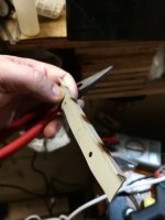
I pulled the burnt plastic piece out, gently warmed and straightened it out and gave it a good clean, a light sand, and a shot of gray primer. We'll see how it turns out, if not good, I'll fashion a replacement piece of aluminium or something. Maybe another job for 3d printing?
Still haven't figured out a practical solution for the rust hole in the top cover. I think brazing a small piece in may work but it's going to be rather fiddly.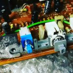
Good job, guy. I suggest as an idea, to place a short piece of aluminum paper or sheet, between the leds and the darkened wall behind the leds, in one of the last pictures.
I pulled the burnt plastic piece out, gently warmed and straightened it out and gave it a good clean, a light sand, and a shot of gray primer. We'll see how it turns out, if not good, I'll fashion a replacement piece of aluminium or something. Maybe another job for 3d printing?
Still haven't figured out a practical solution for the rust hole in the top cover. I think brazing a small piece in may work but it's going to be rather fiddly.


Buttoned up and calling it a day until I find another cover or the weather fines up so I can strip this one bare and tidy it up properly. I haven't updated for a while so here goes.
Gave it a power test into 8 ohm load. 27v RMS @ 1khz (one channel driven) before clipping - which is over 90 watts! Not bad for a 50W rated amplifier. Both channels achieved this, albeit seperately.
Had to retouch a LOT of solder in this thing. As I went, joints kept failing. All okay now though.
I also ended up increasing Miller capacitance to 220pF after it started oscillating again when playing into a load... That seemed to stabilize it. I haven't been able to test yet if it's hurt the performance, but it sounds absolutely fine.
1. Pushbutton replacement - after a few failed attempts at 3d printing an adapter, ended up using hotglue... Actually it works just fine.
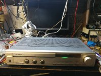
2. Lid on and operating
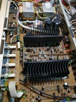
3. Internals
4. New CDE filter caps
5. LED indicators
6. Knobs came up okay, not great tho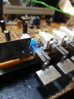
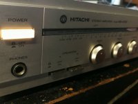


I've only listened to much older Hitachi amplifiers than this one. Those were CFP output stage designs and sounded quite good compared to other typical Japanese consumer audio designs of the 1970s-80s period.
What are your impressions of the sound quality of this one (looks like NEC's version of RET power transistors in the pic) and was it worth the many hours of hard work in restoring a budget model like this one?
What are your impressions of the sound quality of this one (looks like NEC's version of RET power transistors in the pic) and was it worth the many hours of hard work in restoring a budget model like this one?
What are your impressions of the sound quality of this one (looks like NEC's version of RET power transistors in the pic) and was it worth the many hours of hard work in restoring a budget model like this one?
So far I've only listened in the garage. No obvious problems but I'll need to move it indoors to get a better read on the "sound" as neither the speakers or acoustics are up to the job.
It has a lot of power (more than rated), the output noise is very low indeed, and If the specs are to be believed it offers low (0.02%) distortion and reasonably flat response across the audible band. So it "should" sound quite good. I intend to perform some more thorough testing once I get my rig together, and I will post it for interests sake.
The phono stage offers MM or MC input and seems to have been carefully designed to minimize noise.
This was the 2nd tier Hitachi integrated in that year's lineup, the top model was rated 80wpc and used a mosfet output stage. This model and it's smaller brother the HA-3700 used a "superlinear" topology with BJT outputs.
The following year most of their integrateds were using IC output stages, and offered worse specifications. I guess this was the tail end of the "golden era" for Japanese hi-fi.
This amp had plenty wrong with it. I had to replace *every* fusible resistor, the solder was bad and I probably ended up touching up 90% of the joints due to cracking. I had to bypass some of the internal connectors which just weren't reliable even after cleaning. It loves to oscillate at several MHz and I had to increase the miller capacitance to make it stop. And this specific amplifier had suffered some pretty serious corrosion to the chassis and cover.
The potentiometers are nice and smooth and after a quick spray of electrolube have no crackles (though the volume control is neither "heavy" nor stepped like the higher end recievers), the push switches are sturdy and have a nice feel to them, the low profile is impressive for something with this much power.
Worth noting, this unit was assembled in New Zealand, so I don't know to what degree, or if that had any impact on the build quality. This was common due to punitive import levies at the time.
Worth it? I will put it down to a good learning experience, the amp was cheap but I have spent more on parts and materials than I would like to admit. Trouble is, the more recognised japanese amplifiers/recievers tend to go for stupid money - even if they are not working.
A problem with the small form factor and lightweight heatsinks, the heatsinks get real hot if it's pushed hard, and in the absence of good ventilation, the amp section becomes an oven. I am sure this contributed to its former death, that or the oscillations (or both in tandem).
If I find a cheap ha3700/ha4700 with good front controls and case, I may grab it just to finish the job properly. I wouldn't bother repairing a 2nd one, although I might raid it for parts.
Managed to wire up a test rig using REW and an external sound card. THD was basically to spec, which was a nice surprise. At 1W and at 50W was around 0.02%, both channels driven with 8 ohm loads. 1khz and 10khz. I'd call that a win!
There was noise but it seemed to be mostly from the test rig, rather than the amp. I have plans to improve the rig which will allow me to perform more conclusive tests.
Now in the lounge with it hooked up on my Mission 700LE speakers and the Chromecast audio. Having the power meter has prompted an interesting observation, the first LED (which says 0.04W) barely lights up at the volume I dare listen when the family is at home [emoji1787] So far I haven't had it even up to a Watt. What Nelson Pass says about the first Watt certainly rings true here! To be fair it's a very quiet environment and a pretty open plan house.
I did notice this before, but the switch I replaced makes a nasty thump sound through the speakers when engaged/disengaged. It's the tone defeat. I'm thinking maybe it's not make-before-break and the old one was, or there's some other issue in that section, but the tone controls work perfectly, it's both channels, and I went over all the solder joints etc, so I do suspect the former. I wonder if there is a good way to fix this aside from finding the right switch which so far has proven difficult [emoji849]
L-R balance was out of whack at low volumes, with left channel lagging by well over 3dB in parts. Found the volume pot was way off below halfway, as measured. It's a quasi log pot with a large "deadspot" around halfway, which I guess is to provide fair warning you're entering 1W+ territory. For now, I bodged 2x680k resistors from the hot end to the wiper on the left channel, they track much closer now.
The sound?
Initial impressions, clean, punchy, detailed. If any criticism, perhaps slightly brittle/bright in the top end? But I need more time with it to really assess, and to listen louder. So far, it seems to have more clarity and better imaging than my other setup.
It's also introduced a bit of a hum issue with my phono preamp, maybe the input is more sensitive, or maybe there's a ground loop. No hum or noticeable hiss with other sources.
For now I think I'll stick with it and pull my other pre and power amp for analysis and servicing. And fit RCA plugs to the turntable so I can use the built in phono stage.
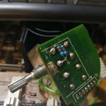
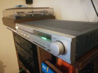


There is too much solder in those joints in the first image. A correctly made join will have a shiny appearance like silver not dull like aluminium.
There is too much solder to reheat the joints so it will adhere properly inside those blobs. The best thing is to remove all of it and start again heating the lead to be soldered first and then bringing the solder into contact.
If you don't do this the component will transfer the heat away and the solder won't flow properly and you will get another blob.
There is too much solder in those joints in the first image. A correctly made join will have a shiny ......
Should have known better than to post less-than-perfect looking joints here [emoji16]
Thank you for the pointer, but in my defense, your honour, I was over it after bodging 4 different values in to get it right, and decided to "just send it anyway".
Found the source of the hum, not my preamp, but the proximity of the tonearm / phono cartridge to the power transformers in the Hitachi. Anyway the preamp has a (very small, but still concerning) wub-wub oscillation every so often, so I need to take it to the workshop anyway.
Got more time to listen today. I'm still finding it bright, but I must say I'm impressed with the dynamics and accuracy of the soundstage. I'm wondering if the channels in my other setup are well matched, phase wise. Now I've got them in the workshop I can check.
In my other preamp, I had added a bass boost which boosted the response from about 100Hz down, to extend the effective bottom end of the speakers. The bass dial does not seem to be doing the same. I have a JBL 12" sub waiting in the wings for it's amp plate, which should help, and/or I will build a bass boost module and stick it on one of the tape loops.
I realised I forgot to test the frequency and phase response before I brought it inside! I will do so this weekend and post, for posterity I guess (and completeness)
- Status
- This old topic is closed. If you want to reopen this topic, contact a moderator using the "Report Post" button.
- Home
- Amplifiers
- Solid State
- Hitachi HA-4700 Repair and Restoration
