Yes exactlyScott - I don't follow. I believe Stuart is saying the chassis protective earth is in place from the mains ground to the chassis ground point. It's this your protection? What is the need for a connection from the power supply 0V to the protective earth chassis connection.
Wouldn't that scenario be better addressed by including fuses after the secondaries? I've seen some PSU designs that include this. And it seems these fuses would do a better job of protecting other downstream connections from damage.
Or is my understanding of this off-track?
Or is my understanding of this off-track?
Scott - I don't follow. I believe Stuart is saying the chassis protective earth is in place from the mains ground to the chassis ground point. It's this your protection? What is the need for a connection from the power supply 0V to the protective earth chassis connection.
This is done because if mains comes into contact with the secondary side, it could expose parts of the circuit to lethal voltages eg the speaker terminals or the headphone jack etc - circuit damage issues aside.
The recommended way is to take the safety earth directly to the chassis and then connect this point to the secondary 0V. This way, if for example the transformer breaks down, the mains is diverted to safety ground and it will trip the GFI.
You of corse should always fuse the primary side (fire hazard protection).
I don’t fuse the secondaries, but instead fuse each amplifier module rail.
Don't fuse the secondaries BEFORE the rectifier and filter capacitors. The capacitor in-rush currents at power-up and the high charging pulse currents will mean the fuse will have to be overrated in order to survive, somewhat defeating the objective of the fuse. The best place to fuse the secondaries is after the filter capacitors.
Wouldn't that scenario be better addressed by including fuses after the secondaries? I've seen some PSU designs that include this. And it seems these fuses would do a better job of protecting other downstream connections from damage.
Or is my understanding of this off-track?
Without a protective earth connection no current would flow to blow the fuse. The RCA jacks would be a live electrocution risk. Furthermore, a fuse won't blow at the tiny currents required to kill someone.
Hi Bonsai.
I have been reading your power point document on how to wire an amplifier and had a question.
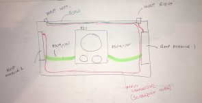
Unfortunately I have already created my rear panel for my Amplifier and my inputs are not next to each other.
I see that you recommend wiring the inputs in a way to minimise loop area.
Can I propose something that would be a compromise but still minimise loop area. See the third image with the red dashed line for the left channel.
I would of course still bond the grounds of each input connector. See the blue dashed line.


I have been reading your power point document on how to wire an amplifier and had a question.
Unfortunately I have already created my rear panel for my Amplifier and my inputs are not next to each other.
I see that you recommend wiring the inputs in a way to minimise loop area.
Can I propose something that would be a compromise but still minimise loop area. See the third image with the red dashed line for the left channel.
I would of course still bond the grounds of each input connector. See the blue dashed line.
Hi.. No sorry my name is Stuart.Hi Stuartmp. I know this is off topic, but seeing you're from the Gold Coast, I'm curious - is your surname Robert? If so, congrats on recent win.


If it helps, I've come across several posts discussing Rod Elliott's circuit. Including this one, where it was tested: https://www.diyaudio.com/forums/pow...erstanding-star-grounding-27.html#post1848434
Wow. AndrewT (RIP) tested that. My question would be why didn't the RCD trip in the meter box. Surely this is meant to trip before that level of current flows.If it helps, I've come across several posts discussing Rod Elliott's circuit. Including this one, where it was tested: https://www.diyaudio.com/forums/pow...erstanding-star-grounding-27.html#post1848434
To clarify my question above. The two AC terminals in the photo from the grounding guide are not connected but in the schematics they are.
In my ground loop breaker (left hand picture above), I have the diodes in the bridge connected in series so each side of the bridge gives +-1.2 volts protection. In the others, they have wired the diodes in parallel and you get +-0.6 voltage across the bridge.
They all do the same thing in that they break the ground loop.
They all do the same thing in that they break the ground loop.
Hi Bonsai.
I have been reading your power point document on how to wire an amplifier and had a question.
Unfortunately I have already created my rear panel for my Amplifier and my inputs are not next to each other.
I see that you recommend wiring the inputs in a way to minimise loop area.
Can I propose something that would be a compromise but still minimise loop area. See the third image with the red dashed line for the left channel.
I would of course still bond the grounds of each input connector. See the blue dashed line. View attachment 762201 View attachment 762202 View attachment 762204
Hello Stuart,
Unfortunately doing what you propose still leaves you with a huge loop area inside the amp and the strong possibility of a cross channel ground loop. If you draw the line diagram, you will see this is the case. You will minimize the externally coupled cross channel ground loop, but this is normally only small compared to the internal cross channel ground loop. Keeping the input loop as small as possible is critical if you want to keep the hum down.
I highly recommend that you put the input connectors next to each other.
Thanks for that I will consider it. I am using a loop breaker. So don't you think that I would be better of to keep my input signal wire away from the transformer and amp supply rails given that I using a loop breaker?Hello Stuart,
Unfortunately doing what you propose still leaves you with a huge loop area inside the amp and the strong possibility of a cross channel ground loop. If you draw the line diagram, you will see this is the case. You will minimize the externally coupled cross channel ground loop, but this is normally only small compared to the internal cross channel ground loop. Keeping the input loop as small as possible is critical if you want to keep the hum down.
I highly recommend that you put the input connectors next to each other.
There are two separate mechanisms at work here.
1. The loop breaker addresses the classis AC ground loop in which a magnetic field cuts the loop formed by the earth connection from your mains plug to the first piece of gear, through the interconnect cable to the earth of the second piece of gear, and then from the second piece of gear back to the mains plug.
2. Putting the input connectors side-by-side, bonding them together and minimizing the internal channel to channel loop area addresses the cross channel ground loop problem. With this problem, a magnetic field (usually the transformer, but can also be radiated fields from the internal wiring to the speaker terminals) cuts the loop bounded by the signal return wires and the amplifier 0V connections in side the amplifier. To prevent this problem, you must (a) use an HBR and (b) minimize the 0V and signal ground loop areas
By all means try it with the connectors apart - it may be quiet enough that its good enough in your system. However, if you put it on an audio analyser like a QA401 or a sound card, you will see that you will be losing about 10-20 dB in noise performance.
Note carefully that just putting the connectors together but not minimizing the internal loop area is also not good enough.
In your case with the connectors set apart, you could try the following (no guarantee it would work because it can depend on a lot of other things in your layout and transformer mag field radiation):-
1. Run the first input cable to the amp module.
2. Route the second channels cable to the first input connector and then run the wire parallel to the first channel cable. Route it around the first channel amplifier and then to the front of the amplifier, along the front plate and to the second amplifier module.
3. Bond the two input connector grounds together (to trap the cross channel ground loop inside the amplifier). Keep the bond and the input cable tightly bound to reduce the loop area.
4. Experiment with the routing between where the cable for the 2nd channel leaves the first amplifier module and goes to the 2nd amplifier module. I recommend you try it around the front plate, but if the transformer mag field is strong, you may actually find running closer to the PSU 0V wire helps because this reduces the loop area even further.
Remember, the shortest route is not always the quietest.
Attachments
Last edited:
Thank you Andrew for that detailed response. I'm going to print that out and at it to my file. I appreciate your time and advice. I'm in the middle of doing some line drawings from my 3D model of my Amplifier.
I will do my best to follow your guidelines and once I'm done I might forward them to you in a PM for a final review if that ok.
I will do my best to follow your guidelines and once I'm done I might forward them to you in a PM for a final review if that ok.
")
- Status
- This old topic is closed. If you want to reopen this topic, contact a moderator using the "Report Post" button.
- Home
- Amplifiers
- Solid State
- How to wire up an Amplifier