I have not tried Self’s way or really thought about it in detail, but since he’s been doing this stuff commercially for a long time I have no reason to doubt it works. There’s a presentation somewhere on the web by a Japanese guy showing it wrt a tube amp.
You would still have to control the loop areas in the amp and think about cross channel ground loops.
You would still have to control the loop areas in the amp and think about cross channel ground loops.
Last edited:
Here is a look at Poldaaudio's set-up and how I'd approach it.
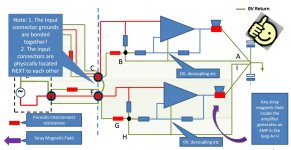
I have an amp with a similar set-up to that shown in the diagram. But, I located the input connectors next to each other and bonded the connector grounds together and then ran the screened cable directly to each amplifier module input - so the shortest route from connectors to modules. If I ran the screened cables together to the fist module and then continued the second screened cable around the front of the amp all the way around to the second module, it was much quieter (talking -110 dBV vs -90 dBV). In the second approach, the loop area between the two amp modules in minimized, so the cross channel loop current is minimized. I use 15 Ohm HBR's but also got good results with a 3.3 Ohm.
If you bond the input connector grounds together, and locate them next to each other, you trap cross channel ground loops inside the amplifier. In the attached diagram, having them separated and not bonded means you have a large loop area for noise pick-up.
Hi Bonsai,
Thanks for your describe. I tried using this way. The amp is dead silence. Using HBR is also usual way in DIY amps.
However in commercial amps i've seen, can't see any of HBR and speaker return to 0V power supply. Clearly it still available a large loop between 2 input.
How they reduce ground loop?
Attachments
Walkalone,
Through very careful layout optimization. I have a Marantz PM7000 that is very quiet. I know that they built about 100k units, so the incentive to get it right at minimum cost is certainly very high. The Marantz uses a GOSS band to reduce radiated noise (EI core).
HBR’s are used quite often in commercial gear - I’ve seen circuits showing them but of course some designs don’t have them - it’s just a case of a different approach like the Self scheme mentioned in an earlier post above.
Last edited:
Thanks for sharing the knowledge here Bonsai.
I always got the impression that using hum breakers was a last resort and I felt like I had failed in some way whenever I'd used them to rectify a noisy project that I just couldn't tame.
So it's nice to read that they are not always used as a last resort but can be integral to a design.
Remember that the Hum Breaking Resistor inside the amplifier will act to reduce the loop currents and divide any internally arising noise voltage down – so always make sure this is fitted.
I always got the impression that using hum breakers was a last resort and I felt like I had failed in some way whenever I'd used them to rectify a noisy project that I just couldn't tame.
So it's nice to read that they are not always used as a last resort but can be integral to a design.
It’s knowledge I hovered up from all sorts or sources - so I wont claim it’s mine ")
I short my HBR’s out and get the noise as low as possible then un-short them. I usually start off with a pair of headphones connected directly to the output. You can dress your wiring etc then for lowest noise - if you do a good job, you have to progress to a sound card as the noise level drops below audibility.
I short my HBR’s out and get the noise as low as possible then un-short them. I usually start off with a pair of headphones connected directly to the output. You can dress your wiring etc then for lowest noise - if you do a good job, you have to progress to a sound card as the noise level drops below audibility.
Last edited:
I took a look at Selfs method and it makes perfect sense.
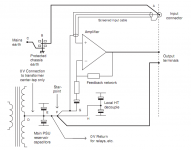
Usually you run the signal ground back to the amp module and to the [perhaps via an HBR as I do] system ground through the PCB, making sure of course to obey all the star ground and associated PCB layout rules. You take your main ground to the chassis after T’ing off the reservoir cap grounds. You then take the incoming mains ground and connect it to the same point on the chassis so there is only one ground connection to the chassis.
How he is doing it is he is placing this ground connection at the input - so he now has the power earth connection to the chassis, the T off from the reservoir ground (ie the main amplifier ground) and the incoming signal ground all located at the signal ground where it comes into the amplifier.
This then causes externally generated ground loop currents arising in the area bounded by the power earth wiring between equipment and the signal interconnect ground to flow away from the small signal circuits - sort of like a revolving door - ‘straight in and straight out buddy’.
But, any ground loop current flowing in the interconnect screen will still cause noise, so it does not prevent this type of problem arising due to external magnetic fields cutting the loop.
I think you will still have to deal with internal cross-channel ground loops, and an HBR will help. But careful layout and cable dressing should be carried out before doing that (link the HBR first out as I mentioned before).
Last edited:
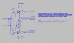
After a closer look, this is actually very close to what I already proposed in another thread. But my proposal had solutions for some issues:
1: The distance between point H and point F interferes with the Boucherot cell.
2: No hum breaking resistor, which is bad for sources with ground noise.
However there is an issue with both layouts that they remove the speaker return current from the umbilical and in so doing create a large current loop which will radiate the speaker current, as well a load current related noise voltage at the board 0V connection. However the harmonics from this current are mild compared to the rectifier pulses and class AB haversines.
Attachments
Last edited:
I presume they are referring to this?
That’s strange - my diagram does not have that error.
After a closer look, this is actually very close to what I already proposed in another thread. But my proposal had solutions for some issues:
1: The distance between point H and point F interferes with the Boucherot cell.
2: No hum breaking resistor, which is bad for sources with ground noise.
However there is an issue with both layouts that they remove the speaker return current from the umbilical and in so doing create a large current loop which will radiate the speaker current, as well a load current related noise voltage at the board 0V connection. However the harmonics from this current are mild compared to the rectifier pulses and class AB haversines.[/QUOTE
HBR’s and correct ground connection sequencing have to go hand in hand with minimizing the internal loop areas. If do all the stuff in the book but don’t take care of loop areas, you can still get a sub-optimal result.
I would insert the HBR - if needed - between where the screen connection is and F.
The whole amplifier is floating after this point and the chassis is earthed. If you have an internal mains to chassis short, it’s still safe. If the source ground is live, it’s earth era via the input signal ground to chassis.
It’s pretty poor design IMV to rely on safety grounding through the signal connectors. Anyone sold commercially must be earthed or it must be double insulated. But I don’t think this is how Self suggests you make a product safe.
I have not seen any of the Signal Transfer Company boards, so could not comment on the grounding arrangements - anyone have more details?
I would insert the HBR - if needed - between where the screen connection is and F.
Same as in my layout.
The whole amplifier is floating after this point and the chassis is earthed. If you have an internal mains to chassis short, it’s still safe. If the source ground is live, it’s earth era via the input signal ground to chassis.
In my layout this is fixed by putting chassis between the hum breaker and point F.
It’s pretty poor design IMV to rely on safety grounding through the signal connectors. Anyone sold commercially must be earthed or it must be double insulated. But I don’t think this is how Self suggests you make a product safe.
Luckily that doesn't seem to be necessary with my changes.
“ The distance between point H and point F interferes with the Boucherot cell.“
If the speaker return is taken back to the on board decouplers and not as Self has shown, the Zobel loop area is contained (trapped) on the amplifier module local HT decoupling loop, so there is very little or no current from this loop in the connection between H and F.
He has shown the speaker return back to the central 0V, so I agree with your point. However, the devil on this will be in the implementation detail. How long is H to F, local decoupling and loop area etc etc.
- Status
- This old topic is closed. If you want to reopen this topic, contact a moderator using the "Report Post" button.
- Home
- Amplifiers
- Solid State
- How to wire up an Amplifier