hi all. i making amp from internet. they make it work on video but mine not working. i rebuild 3 times but same problem. some times fuse burn some times 5200 transistor burn. i try to check voltage and see one thing. on driver board 90v dc i reading but after 10ohm 1W resistor i read 1v some times it go up 3v dc. pls check the circuit. i cannot find what is the problem.
Attachments
You should use a current limited supply to minimise damage, something we advise every time when repairing and diagnosing faults.
djoffe's suggestion to test the driver board is a good one because the board should work as a self contained unit. Although it won't drive speakers it should still give a normal output voltage when viewed using a scope and it should also have zero volts DC offset at the output.
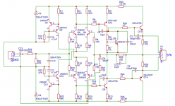
The DC voltage across R27 and R28 should be very low when the bias is set to minimum although as drawn the circuit shows fixed bias... which seems madness tbh.
djoffe's suggestion to test the driver board is a good one because the board should work as a self contained unit. Although it won't drive speakers it should still give a normal output voltage when viewed using a scope and it should also have zero volts DC offset at the output.
The DC voltage across R27 and R28 should be very low when the bias is set to minimum although as drawn the circuit shows fixed bias... which seems madness tbh.
Get the driver board working on its own. It should be able to drive a dummy load or even a small speaker at lower voltage for testing. You should get a usable signal at the SPK pad.
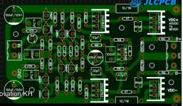
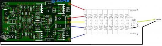
Note that the B+ and B- pads on the driver board are NOT for the power supply, they are the drive signals to the output board. The power supply should be connected to the gold pads at the top/bottom of the board which then connect to those 10 ohm 1W resistors.
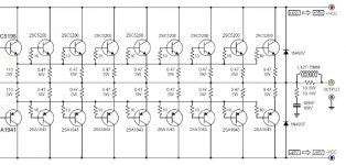
Are you sure that your 2SA1943/2SC5200 devices are genuine ? They are commonly faked using TIP2955/TIP3055 dies, which will simply blow up especially at +/- 90V supply voltages.
Note that the B+ and B- pads on the driver board are NOT for the power supply, they are the drive signals to the output board. The power supply should be connected to the gold pads at the top/bottom of the board which then connect to those 10 ohm 1W resistors.
Are you sure that your 2SA1943/2SC5200 devices are genuine ? They are commonly faked using TIP2955/TIP3055 dies, which will simply blow up especially at +/- 90V supply voltages.
Hi,
I have not simulated the circuit but some aspects that may need to be considered :
Shadders.
I have not simulated the circuit but some aspects that may need to be considered :
- The transistor Q9 which is the Vbe multiplier - is it on the same heatsink as the output transistors ?
- For the Vbe multiplier, is R7 a variable resistance or potentiometer ?
- Are you setting the bias current correctly as per the Vbe multiplier ?
Shadders.
thank you for the answer my friends i am going to check again now with lower voltage.
B+ and B- not connected to the power thank you for warning. but i dont know my power transistors are genuie. i just find thats in my country.
i have second driver pcb and now trying to make it with other new parts.
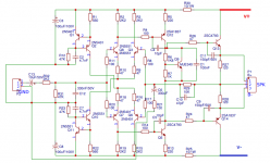
but still i dont understand why after R30 and R25 i cannot get a dc voltage. if i use 40v i need to read after R25 and R30 same voltages. i am wrong abouth that?
B+ and B- not connected to the power thank you for warning. but i dont know my power transistors are genuie. i just find thats in my country.
i have second driver pcb and now trying to make it with other new parts.
but still i dont understand why after R30 and R25 i cannot get a dc voltage. if i use 40v i need to read after R25 and R30 same voltages. i am wrong abouth that?
Attachments
hi shadders. thank you for helping.
1. no q9 dont have heatsink. other 4 transistors have small heatsink but they dont get hot.
2. R7 1k variable
3. i am not good enough that much in electronic. i just find this on youtube and make it. i did before different one but this one i dont know what is problem.
i draw this circuit with isis. if its help i can send it.
Hi,
You have stated :
Regards,
Shadders.
You have stated :
This points to perhaps an incorrect installation of a component which takes power after the 10ohm resistor. Maybe check every component and ensure that it is connected correctly.i try to check voltage and see one thing. on driver board 90v dc i reading but after 10ohm 1W resistor i read 1v some times it go up 3v dc. pls check the circuit
Regards,
Shadders.
Well, this is IMPOSSIBLE and wonder why nobody jumped at it: 90V difference across a 1 ohm resistor means 8100W dissipation.on driver board 90v dc i reading but after 10ohm 1W resistor i read 1v

Even humble 30V would mean 900W
On a humble 1W resistor.
90V difference across a 1 ohm resistor means 8100W dissipation.
Or the resistor (or one of its connections) could be open.
Measure (with power off) the value of the resistance instead.
Hi,ty shadders. that R30 and R25 was a 1w in circuit. after i see there is no voltage i said maybe they are come bad and i put there 10R 2w. now i remember after that fuse blow and i start getting problems. and the R5 and R13 frying.
If R5 and R13 are getting hot and burning out, then this indicates a short in their path. Have you checked your solder joints to ensure you have not bridged connections ?
What about the parts you have used - where did you purchase them ?
That is, did you use a reputable supplier (not ebay) ?
Regards,
Shadders.
i check all companents and see that 1w 10R broken i put there 2w 10R and test the driver alone with 60v dc + -.
driver working now. but i want to be sure abouth my connection driver to power board. i try to show on picture..
and another thing is if i put 90v dc + - it can be problem again?)) lol i burn too much things for this one and cannot be sure abouth it.
driver working now. but i want to be sure abouth my connection driver to power board. i try to show on picture..
and another thing is if i put 90v dc + - it can be problem again?
)) lol i burn too much things for this one and cannot be sure abouth it.Attachments
yes i find that resistors are bad and i change it. i see one of my driver board have problem the signal coming bad and ugly. i will rebuild it with new parts. other one is working good.
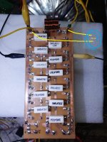
but i cannot be sure abouth power board. i connect power board alone to 90v dc + - and i read -25v dc from out. this is normal? can i connect to the driver board?
but i cannot be sure abouth power board. i connect power board alone to 90v dc + - and i read -25v dc from out. this is normal? can i connect to the driver board?
Attachments
Hi,
If R5 and R13 are getting hot and burning out, then this indicates a short in their path. Have you checked your solder joints to ensure you have not bridged connections ?
What about the parts you have used - where did you purchase them ?
That is, did you use a reputable supplier (not ebay) ?
Regards,
Shadders.
ty for taking care abouth my problem my friend.
i buy from istanbul who selling parts to electronic repair shops.
No that is not normal. Not with nothing connected to the bases of the output transistors. One or more output transistors are leaking. If your OT bases are 0.6 v or above (or minus for pnp) then something ahead of there is leaking or off balance.yes i find that resistors are bad and i change it. i see one of my driver board have problem the signal coming bad and ugly. i will rebuild it with new parts. other one is working good.
but i cannot be sure abouth power board. i connect power board alone to 90v dc + - and i read -25v dc from out. this is normal? can i connect to the driver board?
One test to determine overstressed (leaky) or counterfeit transistors is the Iceo test. Get a 12v or 24 v power supply, a wall transformer will do. Put the milliammeter scale of a DVM or VOM in series with a 47 k resistor. Connect the + of the supply to the ammeter/resistor then to the collector of the npn transistor (individually). Isolate the base of the transistor. Connect the minus of the supply to the emitter of the transistor. Read current. If greater than 24/47000 (or 12/47000 for that supply) the transistor is garbage.
Use the minus of the supply series the meter/resistor on the collector of the pnp transistors. Plus of supply goes to emitter. Same current. The transistor under test should not leak.
I found the local parts store selling some good parts and some garbage. I am relieved now that the debit card & internet were invented, I can buy directly from newark (farnell USA) mouser digikey or alliedelec. In the UK RS is the biggest authorized distributor.
In some countries at the border good parts get substituted for counterfeit - possibly by the customs guys? One guy on here tests every lot of transistor with the Iceo test. Better to buy from an authorized distributor outlet in your own country, let the pros fight the customs problems. They have security seals and other invisible checks on their product.
To Jaycee's point (post #5) if your vendor sold you TIP3055 dies marked 2sc5200, then they would pass a 24 v Iceo test, and fail a 90 v Iceo test. 90 v is dangerous, make sure you touch no voltage over 24 with two hands. Current across your heart can stop it. Don't wear rings or jewelry, current over 1 v through metal jewelry can burn your flesh to charcoal. Don't work alone, and don't work distracted by children or entertainment.
Last edited:
Hi,but i cannot be sure abouth power board. i connect power board alone to 90v dc + - and i read -25v dc from out. this is normal? can i connect to the driver board?
I would not use +/-90volts for the power - drop to +/-60volts to ensure that you are not over stressing the components.
Using a lower voltage will reduce the current - perhaps +/-30volts to begin with.
The -25volts output - what DC offset correction circuit are you using ?
Regards,
Shadders.
Last edited:
ty for all of you my friends.
indianajo, i will take out transistors and check all of them i think negative parts are leak voltage cause of the -25v output yes? or do i need to check all of them + and - transistors.
shadders, i make it with a old transformer. i use one bridge diode and then use 6 capasitors 8200uf 100v and finish it 15k resistors from + to gnd and - to gnd.
i will keep testing vit lower voltage. ty for warnings my friends.
Hi,
Just to state - the design is missing the DC offset null circuitry, and the resistor R7 is not designed on the board to be a potentiometer (adjustable resistor).
By connecting the power to the circuit, you are relying upon perfect components for no DC offset. You are seeing -25volts as you have measured, as the components are not perfect.
You do need the DC offset circuit - as once you connect the output stage - this will be affected by the DC offset of the driver board.
Where did you get the circuit and PCB's from ?
Regards,
Shadders.
- Status
- This old topic is closed. If you want to reopen this topic, contact a moderator using the "Report Post" button.
- Home
- Amplifiers
- Solid State
- need help for amplifier