Hi,
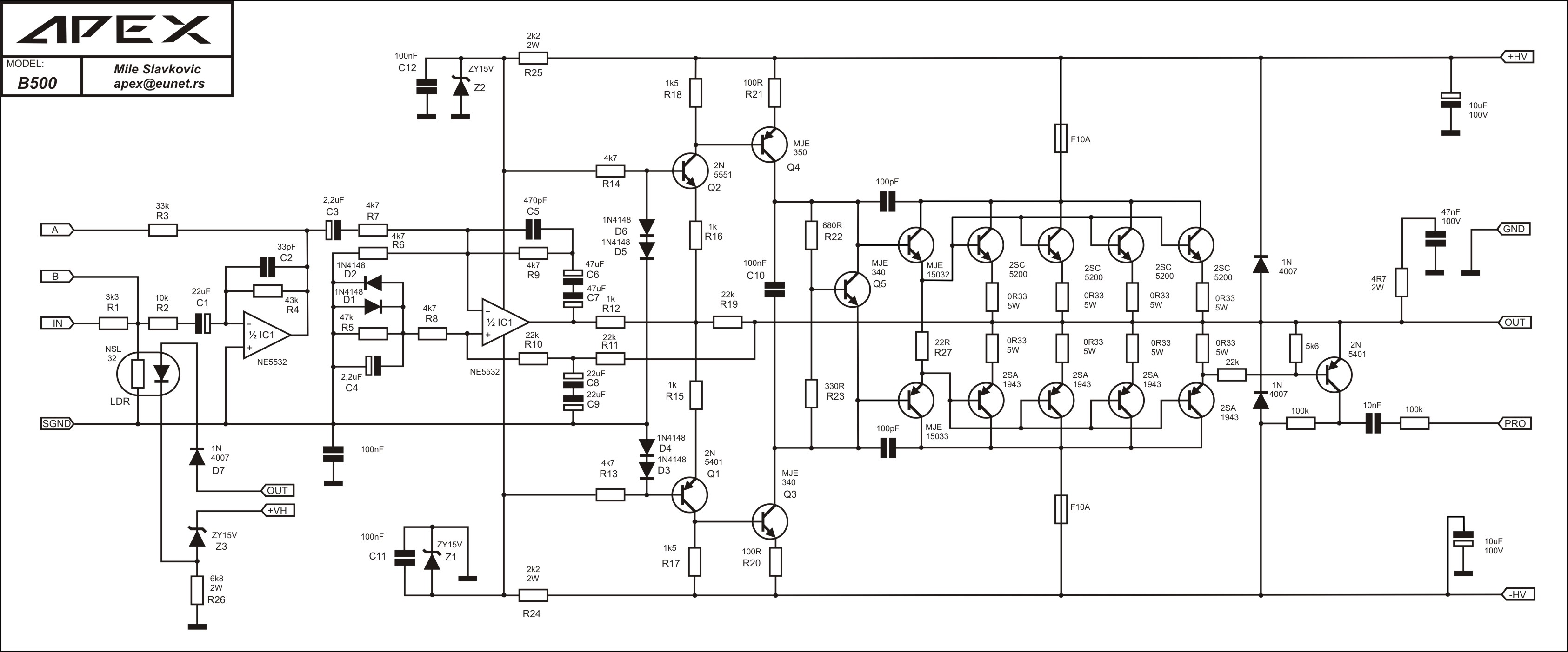
Just to state - the design is missing the DC offset null circuitry, and the resistor R7 is not designed on the board to be a potentiometer (adjustable resistor).
By connecting the power to the circuit, you are relying upon perfect components for no DC offset. You are seeing -25volts as you have measured, as the components are not perfect.
You do need the DC offset circuit - as once you connect the output stage - this will be affected by the DC offset of the driver board.
Where did you get the circuit and PCB's from ?
Regards,
Shadders.
hi,
you mean i need to connect it to the driver board and check the voltage from output?
the circuit from one youtuber. pcb i print and melt it in home.
Hi,hi,
you mean i need to connect it to the driver board and check the voltage from output?
the circuit from one youtuber. pcb i print and melt it in home.
Yes, but the components are not perfect, so, even if you check the driver board and it is 0volts on the output with the power connected, then connecting to the output stage may still have a DC offset.
I do not see any DC offset circuitry, nor a variable resistance for the Vbe multiplier (R7).
You have done very well in creating the PCB yourself from a youtube video.
Regards,
Shadders.
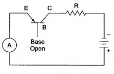
One test to determine overstressed (leaky) or counterfeit transistors is the Iceo test. Get a 12v or 24 v power supply, a wall transformer will do. Put the milliammeter scale of a DVM or VOM in series with a 47 k resistor. Connect the + of the supply to the ammeter/resistor then to the collector of the npn transistor (individually). Isolate the base of the transistor. Connect the minus of the supply to the emitter of the transistor. Read current. If greater than 24/47000 (or 12/47000 for that supply) the transistor is garbage.
hi my friend,
the tester like this?
Attachments
Hi,
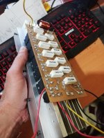
I watched the video for about 2 minutes at the point you started it. Of note is that the central copper conductor is connected to the heatsink. This means that the output of the amplifier is conducting to the heatsink. This is probably catastrophic when you connect anything to the heatsink such as the chassis of the amplifier which is grounded.
Again, there is no DC offset null circuit, there is no potentiometer (R7) to adjust Vbe for the bias current in the output stage, and there does not seem to be a DC servo - which is an active circuit to stop the DC offset.
I am not sure this is a good first construction circuit for a beginner. Maybe people can provide a link to a better solution - as this circuit needs quite a few extras to get it working.
Regards,
Shadders.
hi shadders,
i make one dc protect board too with upc1237. it looks good for dc protect and trying to find and add short protection too.
abouth R7i dont understand my friend. you mean its not enough and need to be potentiometer? on driver board i read 0v witouth input.
i dont know Vbe for the bias current in the output stage. can you explane a little? what it should be? and what will be voltage.thank you..
Attachments
Last edited:
That will work but I connect the meter to the resistor. Cuts the number of alligator clip leads I need to use.hi my friend,
the tester like this?
Hi,hi shadders,
i make one dc protect board too with upc1237. it looks good for dc protect and trying to find and add short protection too.
abouth R7i dont understand my friend. you mean its not enough and need to be potentiometer? on driver board i read 0v witouth input.
i dont know Vbe for the bias current in the output stage. can you explane a little? what it should be? and what will be voltage.thank you..
OK - if you have a UPC1237, then this when connected will protect the loudspeaker from a DC offset, but will not stop it from occurring.
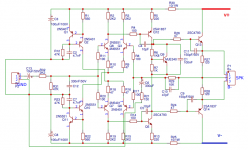
For my reference to R7, the Vbe multiplier is exactly that, the voltage across Q9 Collector and Emitter will be something like 3.6volts - example only. That 3.6volts should be +1.8volt and -1.8volt in respect to ground. The +1.8volts will turn on Q13, the 2SC5198, and the 2SC5200 transistors. Same for the -1.8volts and the opposite/mirror transistors. Each will require about 0.6volts each to turn on. The design will require that R7 is not exactly 1kohm - since the components will vary from batch to batch, and you may get 4volts across Q9, which is too much voltage across the base-emitters of the three transistors (Q13, 2SC5198, 2SC5200) - same for the negative. It could be that the component variation means the voltage is 3volts - not enough to tall all three connected transistors on. R7 is fixed - you need to be able to vary R7 to set the correct voltage, and this turns on the three cascaded transistors, and sets the bias current through the output stage.
This setup of the bias current from the Vbe multiplier is done using a potentiometer where R7 is located, and a method is to measure the voltage dropped across the output resistors (the 0.47ohms, 5watts). A bias current of 80mA is such a value, so that 80mA x 0.47ohms = 37.6mV across the output resistors.
That is the very basics. Did the instructions with the youtube video provide any of this information - there were google storage documents in the comments section of the video page.
This is really too much to write up on a forum - you do need a book to read - i suggest the new Bob Cordell book due out in June 2019, or the latest Doug Self book - both are audio amplifier design books.
Someone else may provide better online references to help you more.
Regards,
Shadders.
hi shadders,
abouth what you told me last time, i find anothr circuit and all is same but one thing. R7 that on my circuit here is 1.8k and they change my R6 1k8 to 3K3 and add that one series 1k pot. i think this is what you saying missing in my circuit yes?
all components are same with mine only R6 and R7 changed.
and i check all pover transistors are good. i did that test too if they are leak but they are not. still on the final board (not driver board) i getting 25v dc.
Attachments
Hi,
OK - if you have a UPC1237, then this when connected will protect the loudspeaker from a DC offset, but will not stop it from occurring.
For my reference to R7, the Vbe multiplier is exactly that, the voltage across Q9 Collector and Emitter will be something like 3.6volts - example only. That 3.6volts should be +1.8volt and -1.8volt in respect to ground. The +1.8volts will turn on Q13, the 2SC5198, and the 2SC5200 transistors. Same for the -1.8volts and the opposite/mirror transistors. Each will require about 0.6volts each to turn on. The design will require that R7 is not exactly 1kohm - since the components will vary from batch to batch, and you may get 4volts across Q9, which is too much voltage across the base-emitters of the three transistors (Q13, 2SC5198, 2SC5200) - same for the negative. It could be that the component variation means the voltage is 3volts - not enough to tall all three connected transistors on. R7 is fixed - you need to be able to vary R7 to set the correct voltage, and this turns on the three cascaded transistors, and sets the bias current through the output stage.
This setup of the bias current from the Vbe multiplier is done using a potentiometer where R7 is located, and a method is to measure the voltage dropped across the output resistors (the 0.47ohms, 5watts). A bias current of 80mA is such a value, so that 80mA x 0.47ohms = 37.6mV across the output resistors.
That is the very basics. Did the instructions with the youtube video provide any of this information - there were google storage documents in the comments section of the video page.
This is really too much to write up on a forum - you do need a book to read - i suggest the new Bob Cordell book due out in June 2019, or the latest Doug Self book - both are audio amplifier design books.
Someone else may provide better online references to help you more.
Regards,
Shadders.
hi my friend.
i dont know how to thank to you. i think i understand that. you should be a teacher in school cause no one make me understand that in my LANGUAGE lol... so if i take out that R7 and put a 1Kpot or 5K and then when i changing resistor value i check the voltage and stop where i need and seal it. it will be ok for me? and how can i calculate what voltage i need there on it.
i will buy that books and read. but i dont know if i can understand in english. some times i dont understand nothing my english is not perfect.
The 25 v with no bases connected to the output transistors suggests they are not good. Double diode test with a dvm is only a preliminary screen for absolute garbage. 12 v Iceo caught all the leaky On semi transistors in my PV-1.3k but perhaps you need to use 90 v Iceo test since you might have counterfeit 2SC5200s.
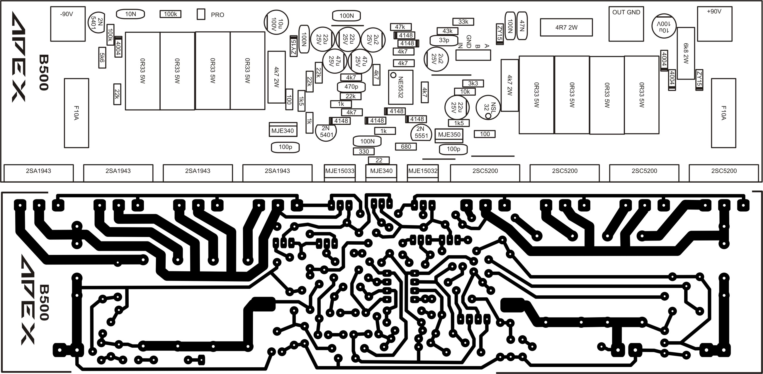
You can isolate exactly which output transistor is leaking by looking at the voltage on the various emitter resistors of the output transistors. The leaky one will have non-zero voltage. The emitter resistor voltage should be zero with no base drive current.
For reliability reasons, designers usually put the idle current adjustment pot parallel to the resistor in the Vbe multiplier circuit. Pot wipers tend to lose connection to the body over time. Putting the pot parallel to a resistor and connecting the pot wiper to one end of the pot also, limits the idle current to a maximum, that happening with the end to end resistance of the pot.
I clamp the adjustment pot with a diode or stack of diodes (including maybe a zener), in addition. This costs an extra $.80 but this is diyaudio, I don't have to make a profit. And overheated broken output transistors are $4.50 each, making the extra $.80 of diodes worth it IMHO.
As far as inexpensive learning, I like to look at successful circuits. Look at some of the 1000-2500 W class AB PA amps over on PA thread. The successful vendors are Crown, Peavey, QSC, Yamaha. Note they control their output transistor idle current by selecting parts at the factory incoming inspection room, a luxury a diy builder does not have.
Last edited:
Hi,hi shadders,
abouth what you told me last time, i find anothr circuit and all is same but one thing. R7 that on my circuit here is 1.8k and they change my R6 1k8 to 3K3 and add that one series 1k pot. i think this is what you saying missing in my circuit yes?
all components are same with mine only R6 and R7 changed.
and i check all pover transistors are good. i did that test too if they are leak but they are not. still on the final board (not driver board) i getting 25v dc.
Yes - the resistors R7 and R6 are critical to ensuring that all the following cascaded transistors are turned on, but not too much, so the bias current is for example 80mA through every output transistor. This is why simulation is also critical - to determine the approximate resistances to use get the correct Vbe voltage.
As indianajo has said - without the driver board connected - then with the power to the output stage applied, the output voltage should be 0volts. If you follow his advice, then this will allow you to test the board to ensure that all is ok before progressing further.
I understand there is a language barrier - but i think Doug Self book is imprinted in other languages - someone here copied a few pages with different language text.
Regards,
Shadders.
Hi indianajo,
Hi shadders,
i think my diodes have problem. i was check them before but there nothing else on this board resistors good transistors good diodes look good but i cannot trust diodes never they allways let me down)) so when i go home i will check that diodes 1N4937 i will check datasheet maybe they are not good on this board for 90v or i dont know my friends it need to be work there is only 3-4 component and i am getting crazy for i cannot make them work good
ty for still trying to help me...
Hi shadders,
i think my diodes have problem. i was check them before but there nothing else on this board resistors good transistors good diodes look good but i cannot trust diodes never they allways let me down
)) so when i go home i will check that diodes 1N4937 i will check datasheet maybe they are not good on this board for 90v or i dont know my friends it need to be work there is only 3-4 component and i am getting crazy for i cannot make them work good ty for still trying to help me...
With 8 output transistor pairs you need >200 PIV 6 amp or greater diodes at the output. They are there to prevent the speaker inductance from causing a voltage during a rapid shutoff that exceeds the Vceo ratings of the output transistors. Inductances tend to maintain the same current. The diodes dump such a current before it reaches the output transistors.
You must have big honking speakers to need 8 output transistor pairs. My PV-1.3K makes do with 5 pairs MJ15024/25 .
You must have big honking speakers to need 8 output transistor pairs. My PV-1.3K makes do with 5 pairs MJ15024/25 .
Last edited:
I guess the OP bit more than he can chew with this project.
Which to boot comes from a very poor quality "You Tube" source.
I guess "nobody" actually built this amplifier and used it professionally, such as , say DJ duty in a Club, PA for a band, etc.
"1200W RMS" is close to nonsense, but of course a beginner´s magnet, specially as it is shown as an "easy" project.
Yes, +/-90V rails and a mountain of transistors may produce 1200W RMS output.
Now to the "small but awkward details"
* the power transformer shown can handle, being optimistic, some 780VA, so good for 500/600W RMS, tops.
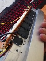
* the heatsink shown is ludicrous, very thin aluminum, closer to window/door extrusion (which it might very well be) than to large power amplifier heatsink, it´s not shown how the full amp can be mounted in a chassis, even less in an enclosure.
As shown lying fins down on a piece of wood it will dissipate nothing; it might survive if placed vertical (fins horizontal) with two PC type fans blowing into fins.
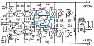
* the "power test" is a joke , builder drives it with way too low level earphone out, into a cheesy loudspeaker, and "measures power" with an Electrician´s clamp on current meter (what´s wrong with using an AC voltmeter ?)
And in any case meter shows 0.5 to 0.85 A ... so he´s driving speaker with less than 8W RMS
Absolute best case you can build it, it works (sort of) for 5 minutes on a table top, and you can brag about it.
As shown, I don´t see how could it be put to any *practical* use.
Notice I am not saying a single word about electrical design, not even about the PCB, simply stating some *physical* impossibilities .
Now if you use it with way lower supply rails, say +/- 50 to 60V, and pull 200/300W RMS, even so a fan will help, that is more believable and usable in practice.
In which case 2 power transistor pairs will be enough; use 3 pairs if you wish.
I suggest next time yopu check wellproven Apex Audio designs, in this same Forum.
Well documented, sensible designs, built by many, real designer is available on the Forum, what´s not to like?
And all have been built and *used* as DJ or PA amplifiers, for many years now.
Which to boot comes from a very poor quality "You Tube" source.
I guess "nobody" actually built this amplifier and used it professionally, such as , say DJ duty in a Club, PA for a band, etc.
"1200W RMS" is close to nonsense, but of course a beginner´s magnet, specially as it is shown as an "easy" project.
Yes, +/-90V rails and a mountain of transistors may produce 1200W RMS output.
Now to the "small but awkward details"
* the power transformer shown can handle, being optimistic, some 780VA, so good for 500/600W RMS, tops.
* the heatsink shown is ludicrous, very thin aluminum, closer to window/door extrusion (which it might very well be
) than to large power amplifier heatsink, it´s not shown how the full amp can be mounted in a chassis, even less in an enclosure.As shown lying fins down on a piece of wood it will dissipate nothing; it might survive if placed vertical (fins horizontal) with two PC type fans blowing into fins.
* the "power test" is a joke , builder drives it with way too low level earphone out, into a cheesy loudspeaker, and "measures power" with an Electrician´s clamp on current meter (what´s wrong with using an AC voltmeter ?)
And in any case meter shows 0.5 to 0.85 A ... so he´s driving speaker with less than 8W RMS
Absolute best case you can build it, it works (sort of) for 5 minutes on a table top, and you can brag about it.
As shown, I don´t see how could it be put to any *practical* use.
Notice I am not saying a single word about electrical design, not even about the PCB, simply stating some *physical* impossibilities .
Now if you use it with way lower supply rails, say +/- 50 to 60V, and pull 200/300W RMS, even so a fan will help, that is more believable and usable in practice.
In which case 2 power transistor pairs will be enough; use 3 pairs if you wish.
I suggest next time yopu check wellproven Apex Audio designs, in this same Forum.
Well documented, sensible designs, built by many, real designer is available on the Forum, what´s not to like?
And all have been built and *used* as DJ or PA amplifiers, for many years now.
Last edited:
Absolute best case you can build it, it works (sort of) for 5 minutes on a table top, and you can brag about it.
hi,
you think this one will not drive 2 x 4ohm speaker?
if you thinking like that can you suggest any circuit? i need finish and give this to my friend for a birthday gift but it become a pain in my brain. if you know any other circuit i can make with my transistors i i use in driver board i can change it but i cannot buy other components cause i dont have a job in these days so i dont have enough money. dolar going up all days a littlebit so in my country its become expensive.
so if any of you my friends if you know any other circuit that i can use my components. i can change the driver too just i need a power amp 500 600w. my transformer is from old poweramp giving 4 different voltages. 0-14v, 88-0-88, 44-0-44, 62-0-62 volts (AC)
if this one can work we will have another circuit builded and tested. but if i really need to change and make other one please show me which one i can make with minimum payment.
ty for help...
APEX amplifiers have been built by many, Mr APEXAUDIO is a respected Forum Member and answers questions in his threads.
That said ¨*read* them first end to end to avoid needlessly bothering him with questions which have been asked (and answered) before many times.
Chock full of information, many who built them show completed ones and comment on details such as where to get heatsinks, chassis, how to mount them, etc.
Most important is that they have been built and used "in the real world" for many years now
Read his projects and find which one uses a power supply similar to what you have, and transistors also equivalent, which are the most expensive parts; then the rest is relatively inexpensive: TO92/220/39 transistors, resistors, capacitors.
Many of the projects start with the "main" schematic, which already works, and then he (or another Forum member) adds, say, a limiter, balanced inputs, speaker DC protection, etc. ; you add what you want to your own but that can be done to the main amplifier already built and working
In principle search inside "Solid State" posts by user "apexaudio" but to start I suggest these ones as closest to your project ... be certain to read threads end to end at least once and then focus on the part you need:
500W PA amplifier with Limiter
He says these can be used with *up to* +/-90V supplies, but personally suggest you play it very safe and stick to around +/-70V or so, mainly of behalf of the quality of transistors available "out there".
In any case the amplifier is VERY LOUD, those are REAL Watts, forget comparing them to amplifiers being sold claiming 500/900/1200W ... this is the real thing.
Circuits are relatively simple ... which is good because they are easier to build without errors and easy to troubleshoot.

Please read the full thread.
That said ¨*read* them first end to end to avoid needlessly bothering him with questions which have been asked (and answered) before many times.
Chock full of information, many who built them show completed ones and comment on details such as where to get heatsinks, chassis, how to mount them, etc.
Most important is that they have been built and used "in the real world" for many years now
Read his projects and find which one uses a power supply similar to what you have, and transistors also equivalent, which are the most expensive parts; then the rest is relatively inexpensive: TO92/220/39 transistors, resistors, capacitors.
Many of the projects start with the "main" schematic, which already works, and then he (or another Forum member) adds, say, a limiter, balanced inputs, speaker DC protection, etc. ; you add what you want to your own but that can be done to the main amplifier already built and working
In principle search inside "Solid State" posts by user "apexaudio" but to start I suggest these ones as closest to your project ... be certain to read threads end to end at least once and then focus on the part you need:
500W PA amplifier with Limiter
He says these can be used with *up to* +/-90V supplies, but personally suggest you play it very safe and stick to around +/-70V or so, mainly of behalf of the quality of transistors available "out there".
In any case the amplifier is VERY LOUD, those are REAL Watts, forget comparing them to amplifiers being sold claiming 500/900/1200W ... this is the real thing.
Circuits are relatively simple ... which is good because they are easier to build without errors and easy to troubleshoot.
It's my old designs, and isn't better than Crest, QSC, Crown... Just better for DIY, and more easy to DIY.
Please read the full thread.
Last edited:
APEX amplifiers have been built by many, Mr APEXAUDIO is a respected Forum Member and answers questions in his threads.
That said ¨*read* them first end to end to avoid needlessly bothering him with questions which have been asked (and answered) before many times.
Chock full of information, many who built them show completed ones and comment on details such as where to get heatsinks, chassis, how to mount them, etc.
Most important is that they have been built and used "in the real world" for many years now
Read his projects and find which one uses a power supply similar to what you have, and transistors also equivalent, which are the most expensive parts; then the rest is relatively inexpensive: TO92/220/39 transistors, resistors, capacitors.
Many of the projects start with the "main" schematic, which already works, and then he (or another Forum member) adds, say, a limiter, balanced inputs, speaker DC protection, etc. ; you add what you want to your own but that can be done to the main amplifier already built and working
In principle search inside "Solid State" posts by user "apexaudio" but to start I suggest these ones as closest to your project ... be certain to read threads end to end at least once and then focus on the part you need:
500W PA amplifier with Limiter
He says these can be used with *up to* +/-90V supplies, but personally suggest you play it very safe and stick to around +/-70V or so, mainly of behalf of the quality of transistors available "out there".
In any case the amplifier is VERY LOUD, those are REAL Watts, forget comparing them to amplifiers being sold claiming 500/900/1200W ... this is the real thing.
Circuits are relatively simple ... which is good because they are easier to build without errors and easy to troubleshoot.
Please read the full thread.
hi,
i dont read this much even in my school days lol
ty my friend. i chose ba500 its more easy for me i think. i promise to my friend that i will make one amplifier and gift him for his new opening small bar.
so i starting make ba500.
thank you for your time and helping all..
- Status
- This old topic is closed. If you want to reopen this topic, contact a moderator using the "Report Post" button.
- Home
- Amplifiers
- Solid State
- need help for amplifier